Routing and Scheduling Guide
Data Sources
Data Sources provide Raw Messages to DECODES for processing. There are several types:
LRGS – Retrieves raw messages from a remote LRGS server over the network.
HotBackupGroup – An ordered group of LRGS data sources. It switches to a backup server if a primary server becomes unavailable.
File – Read data from a specified file
Directory – Continually scan a directory and process files as they appear
Socket Stream – Connect to a socket and process a stream of data
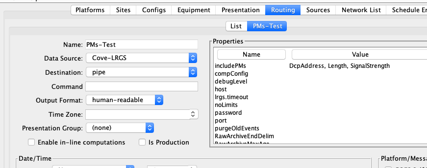
Figure 1 shows a data source that pulls data from the CDADATA machine operated by NESDIS at Wallops, VA. Note the properties that are appropriate for LRGS data sources:
host: host name or IP address of the LRGS
username: The figure shows xxxxxx. You must supply an actual user name given to you by Wallops CDA.
port: (optional) You only need to enter this if it is something other than the default 16003.
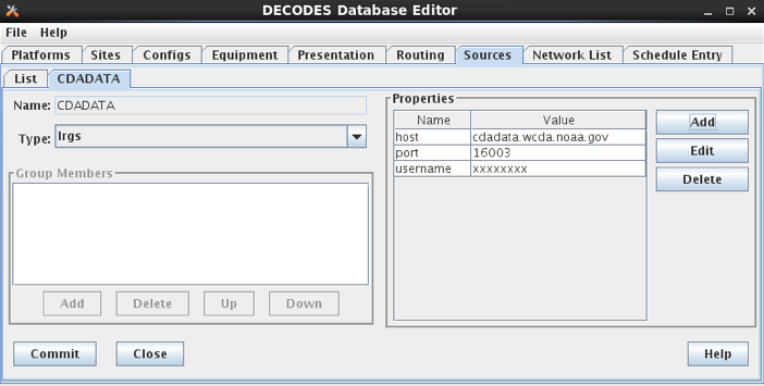
Figure : Data Source Edit Panel showing LRGS Data Source.
The following subsections describe each data source type in detail.
LRGS Data Source
LRGS Data Sources are used to connect to LRGS or DRS systems over the network. The LDDS Server must be running on the LRGS you want to connect to.
Properties for the LRGS Data Source may be placed in the Data Source record or the Routing Spec Record in your DECODES database. Properties defined in the Routing Spec record will override those of the same name defined in the Data Source record.
So, for example, if the Data Source record contains “username=joe”, but the Routing Spec record contains “username=ted”, THEN “ted” will be the username passed to the LRGS server.
Accepted properties are as follows:
host: The host name or IP Address of the LRGS system to connect to. (Optional, If missing, the name of the data source object is used.)
port: Port number for this LRGS’s server. (Optional, default = 16003)
username: registered user on the LRGS server (required)
password: Some LRGS servers are configured to require passwords. If this is the case, you will need to enter the password here. Warning! The password will be stored in clear text in the SQL database and XML files.
single: (Default=false) The newer LRGS servers have a new feature whereby many DCP messages can be returned for a single request. By default, DECODES will use this feature if the server supports it. To force the old (single message per request) behavior, add a property “single” with a value of either “on”, “true”, or “yes”.
sendnl: (Default=true) – Old DRS servers do not support network list transfers. Set this to false when connecting to such servers. The data source will then assume that the network lists are already loaded on the DRS. You must then transfer the list using some other mechanism (e.g. FTP) prior to running the routing spec.
response.timeout: (Default=60 seconds) This is the number of seconds to wait for a response from this server. See discussion of timeouts below.
Each time an LRGS is initialized, it is passed the new search criteria from the routing specification. This information includes the “since” and “until” times, network lists, and the routing spec properties.
The Routing Spec may contain a property called “lrgs.timeout”, set to a number of seconds. If so, this value will be used by the LRGS data source. The default timeout is 60 seconds.
The routing spec will exit with the LRGS Data Source determines that the specified “until time” has been reached. If no until time is specified, the routing spec will continue running indefinitely.
Timeouts in LRGS Data Sources
There are two timeout values that effect the operation of an LRGS Data Source:
The “response.timeout” property in the LRGS Data Source object controls how long to wait for a response from the server after sending a request. The purpose of this timeout is to catch connections that have failed. For example, the server is no longer responding or a WAN link has gone down.
The “lrgs.timeout” property in the Routing Spec object, specifies the maximum number of seconds to wait for the next message to arrive. This means, even if a link is up and the server is responding to each request in a timely fashion, wait no more than this many seconds for the next message. The purpose of this timeout is to catch problems upstream from the server.
The “lrgs.timeout” property is associated with the routing spec (not the Data Source) because it depends on what data you are retrieving. For example, if I am getting data from a single DCP that reports hourly, I might set lrgs.timeout to 3660 (1 hour and 1 minute).
In most cases, the “response.timeout” should be fairly low. The default value of 60 seconds should suffice.
When a timeout (of either type) occurs, the LRGS Data Source throws an exception and…
If this LRGS is part of a Hot Backup Group, the group will attempt to connect to another LRGS.
If this LRGS is the sole data source, the routing spec will terminate.
File Data Source
A File Data Source reads a series of DCP messages from a single file. It processes the file from beginning to end and returns each message found therein. After reaching the end of the file, the Data Source causes the routing spec to exit.
Accepted properties for a File Data Source are as follows:
Name |
ValueType |
Description |
filename |
path |
If present, this value will be used as the file name to be read. It can be a complete path name or a filename relative to the current working directory. If this property is absent, the name of the data source will be assumed to be a file name. The value may also contain environment variables as described in section 0. |
before |
del imiter |
A special string that delimits the beginning of a new message in the file. This string may contain binary and escaped characters such as \n (newline) or \001 (ASCII STX). |
after |
del imiter |
special string the delimits the end of a message in the file. |
MediumType |
name |
Specifies the type of data stored in the file, such as “GOES”, or “data-logger”. |
MediumId |
name |
Specifies the transport medium ID of the platform that generated the messages in the file. Optional: Only use this if all the messages in the file came from the same platform, such as an EDL file. Typically, the MediumId can be constructed from information in the message header so specifying a property is not necessary. |
LengthAdj |
number |
Some header types (like Vitel) report message length wrong. Use this kludge to adjust the length before attempting to read the message bodies. |
OneMessageFile |
B oolean |
Default=false. When set to true, DECODES assumes that the entire file contains one message. |
gzip |
B oolean |
Default=false. Set to true to gunzip the file as it is being read. |
ParityCheck |
String |
“none” (default) = no parity checking. “odd” means do an odd parity check and replace bad characters with ‘$’ and strip partiy from all results. Likewise “even” does an even check. “strip” means to strip parity bits but do no checking. |
For added flexibility, the filename property may contain environment variables preceded with a dollar sign. For example, set the filename property to $FILENAME. Then start the routing spec with the -D argument defining the filename, as follows:
rs -e -DFILENAME=/usr/local/mydata/cr10-1.dat specname
Delimiting Messages Within the File
The ‘before’ and ‘after’ strings are optional. Here is how DECODES interprets them:
If neither ‘before’ or ‘after’ is specified, the entire file is assumed to contain a single message.
If ‘before’ is specified, but ‘after’ is not. DECODES will scan the file for the ‘before’ string and return data following it, up to, but not including the next ‘before’ string. The final message terminates at end-of-file. Any data in the file prior to the first ‘before’ string will be ignored.
If ‘after’ is specified, but ‘before’ is not. The first message starts at the beginning of the file and continues up to, but not including, the first occurance of the ‘after’ string. ny data at the end of the file not terminated by the ‘after’ string will be ignored.
If both ‘before’ and ‘after’ are specified, only completely delimited messages will be processed from the file.
Directory Data Source
A “Directory Data Source” allows you to designate one or more directories on your system into which data files are placed. This is typically used for Electronic Data Logger) files.
You use properties to specify the directories and other settings. The routing spec will continually “watch” the directories for new files to appear. When a file is found it is decoded. The following properties are accepted. The property name is not case sensitive, but in some cases (e.g. a UNIX file name) the property value is case sensitive.
Name |
ValueType |
Description |
DirectoryName |
Path |
The path name to the directory to be watched. The value may contain environment variables (see below). |
FileExt |
String |
Only files with this extension will be processed from the directory. Other files will be ignored. |
Recursive |
Boolean |
If true, then DirectoryName is taken as the root of a hierarchy of directories. All sub-directories (and sub-sub-directories, etc.) are also watched for files. |
NameIsMediumId |
Boolean |
Some EDL files do not have a complete medium identifier in the header. Set this to true if the file-name itself is to be taken as the medium identifier. Note: If a FileExt is specified, it is stripped from the name before using it as a medium ID. |
SubdirIsMediumId |
Boolean |
Use this with the Recursive flag if the sub-directory name is to be taken as the medium ID. |
DoneDir |
Path |
If specified, files that have been successfully processed will be moved to this directory. |
DoneExt |
String |
If specified, files that have been successfully processed will be renamed with this extension. |
OneMessageFile |
Boolean |
Default=false. If true, DECODES assumes that each file in the directory contains a single message. Turn this feature off by adding a property explicitly set to false. |
MediumType |
name |
Specifies the type of data stored in files in this directory, such as “GOES”, or “data-logger”. |
DoneProcessing |
Boolean |
Default=true. ‘False’ will cause the input file to be deleted after processing. |
FileNameDelimiter |
String |
If the medium ID is only the first part of the file name, perhaps followed by a time-stamp, you can specify a delimiter here. The default delimiter is a single period “.”. See the discussion below on File Name Delimiters. |
fileNameTimeStamp |
Boolean |
Default=false, set to true if data between the delimiter and the filename extension is to be taken as the message time-stamp, which must be in the format MMDDYYYYHHMMSS. |
gzip |
Boolean |
Default=false. Set to true to gunzip the file as it is being read. |
ParityCheck |
String |
“none” (default) = no parity checking. “odd” means do an odd parity check and replace bad characters with ‘$’ and strip partiy from all results. Likewise “even” does an even check. “strip” means to strip parity bits but do no checking. |
fileRestSeconds |
Integer |
Allow this many seconds to elapse since last modify time before processing file. This prevents processing of a file that is currently being written. |
Setting up a Tree of Directories for Data Logger Files:
To set up a tree of directories to be watched, set ‘DirectoryName’ to the root of the tree, and set ‘Recursive’ to true. If you want to devote each sub-directory to a specific platform, set ‘SubdirIsMediumId’ to true. Then name each subdirectory with the transport identifier in the platform.
Example: I have two data-loggers. The platform records have medium IDs of “01435532-cr10-1” and “05523352-cr10-1”. The file headers do not contain the STATION identifier. The data files will all end in “.dat”. After processing, I want the files renamed with the extension “.done”.
I can set up a tree as follows:
Parent Dir: $HOME/edl-data
Sub Dir: 01435532-cr10-1
Sub Dir: 05523352-cr10-1
I set up a DirectoryDataSource with the following parameters:
DirectoryName |
$HOME/edl-data |
FileExt |
.dat |
Recursive |
true |
SubdirIsMediumId |
true |
DoneExt |
.done |
I then build a routing spec that uses this data source. When I run the routing spec, it watches for new files to appear. I place the data files in the appropriate sub-directory and they are immediately processed.
Files with Errors:
If a file contains un-recoverable errors, we don’t want the routing spec to abort, as it would if we were only processing a single file. When such an error occurs, DirectoryDataSource renames the file with the extensions “.err” and leaves it in the input directory. FAILURE messages will be generated in the log explaining the nature of the problem.
Only Process Complete Files
We only want to process files that are complete. Consider the following scenario: I am copying a large EDL file from a floppy disk into the input directory. Before the copy is complete, the Directory Data Source grabs the (partial) file and processes it. There are two way to avoid this problem:
Specify a FileExt property like “.dat”. Copy the file in from the floppy disk without the extension, and then rename the file with the extension.
Unix Only: Copy the file to a temporary directory on the same mounted disk partition. Then use the ‘mv’ command to move it into the input directory.
File Name Delimiters
The ‘fileNameDelimiter’ property is used in conjunction with ‘nameIsMediumId’. If only the first part of the name is to be considered the medium ID. Set fileNameDelimiter to the character that separates the mediumID from the rest of the file name. The default is a single period. For example suppose the file from station ‘CORA’ has a time-stamp in the name:
CORA-0905041230.dat
In this case, set nameIsMediumId=true, fileNameDelimiter=- (a single hyphen), and fileExt=”.dat”.
Files with No Header
When processing files that contain no header, you need to set the property OneMessageFile=true. This tells DECODES that the entire file is to be taken as a single message.
Then DECODES needs a way to associate the file to a platform. The medium ID can be found in 3 places:
The file name: Add a property NameIsMediumId=true
The subdirectory containing the file: That is, you might have a hierarchy of directories with a separate subdirectory for each platform. The subdirectory is to be taken as the medium ID. Then set property SubdirIsMediumId=true
If all files from a given data source have the same medium ID, you can set a property “MediumID” with the value.
In the data source record, set medium type to either “NoHeader”, or “Other”.
In the Platform Transport Medium record, set Medium Type to “Other”. If “Other” is not one of the choices in the pull-down list, use the Reference List Editor “rledit” program to add it.
Hot Backup Group Data Source
A Hot Backup Group Data Source is primarily used for a set of LRGS connections. One connection may fail, in which case we want our routing spec to try another. This makes your routing spec more reliable, particularly if this is a real-time routing spec that runs continuously (i.e. no “Until Time”).
Currently there is only one property that is used by a Hot Backup Group:
recheck: (default = 900 seconds, or 15 minutes) – If the currently active data source is not the first one in the list, the Hot Backup Group will attempt to connect to higher priority data sources at this period.
fudge: (default = 120 seconds, or 2 minutes) – Amount of time to back-up after connecting to new data source.
The Hot Backup Group contains an ordered list of LRGS data sources. The group will prefer the members in the order they are listed.
Upon start-up, the group will attempt to connect to a LRGS, starting with the first one listed. Once a successful connection is made, this LRGS becomes active. The group then reads DCP messages from this source until…
The active source fails (either a timeout or broken connection), or
The active source is not first in the list and the recheck period expires.
When this happens, the group will try to connect to a source, once again starting from the first in the list.
When the group changes from one active source to another, it passes the new source the network lists and search criteria with one modification: The ‘since’ time is adjusted to:
LastMessageTime – fudge
… where LastMessageTime is the time of the last DCP message I received. The ‘fudge’ factor (default=120 seconds) can be controlled via a property setting.
The purpose of this fudge factor is to account for small variations in the system clocks of the LRGS members. If you have all your systems synchronized via NTP you can make the fudge factor very small.
Larger fudge factors may result in duplicate messages: A DCP message received from one LRGS and then after a switch, the same message received from the new LRGS.
Round Robin Group Data Source
A round-robin group contains a list of other data sources.
The purpose of a round-robin group is to continually read data from all data sources in the group. This differs from a hot-backup group, which only uses one data source at a time
Socket Stream Data Source
A socket stream data source opens a socket and reads a one-way stream of data containing raw DCP messages. Some DRGS and HRIT product provide such a stream.
Accepted properties for SocketStreamDataSource are:
host = the host name or IP address of the server
port = the port number of the socket to be opened
lengthAdj = a negative or positive number. The default value is -1. (See below)
delimiter = A string that begins each message, use \r for carriage return and \n for linefeed. The default delimiter is \rn. (See below)
endDelimiter = A string that marks the end of each message. This is required if header is “noaaport”. The NOAAPORT message format determines the message length not from the header but from the beginning and end delimiters.
header = GOES, VITEL, NOAAPORT, Vaisala. The default is GOES (See below)
ParityCheck = see description of this property under File Data Source.
Delimiters and Length Adjustments
Each message must start with a 37-byte DOMSAT header. The last 5 bytes of the header is the number of message bytes to follow. Immediately following the message data, a delimiter is expected. The delimiter is not included in the message length.
The Vitel DRGS reports a message length which is actually 4 more than the number of bytes actually present in the message data. Each message is terminated by a carriage return and linefeed. Hence the proper settings for a Vitel DRGS are:
lengthAdj = -4
delimiter = \rn
How messages are parsed
The socket is opened. The input software expects the stream to start with a message header, followed by the message data, followed by the delimiter. This cycle repeats indefinitely until the socket is closed.
The input software can get out of sync in one of the following ways:
Detecting an invalid 37-byte header (no DCP address, channel number, or message length).
Failing to find the delimiter string
When this happens, the input software goes into “hunt mode”. It will read characters from the socket looking for the delimiter sequence. Once found it will again attempt to read the 37 byte header.
Look at the debug-log when running the routing spec. If your ‘lengthAdj’ and ‘delimiter’ parameters are correct you will never see the messages saying that the software has skipped data. If you do see these messages:
Consult the manual for the server system to determine how messages are formatted.
Make sure the delimiter string is correct as described above.
Try adjustin lengthAdj downward, into negative numbers (incrementally).
Network Lists and Time Ranges
Since a socket-stream is assumed to be a real-time data source, the input software will ignore the ‘since’ and ‘until’ times specified in the routing spec.
Network lists will be used to filter incoming data. Only messages whose DCP address is contained in one of the routing-specs network lists will be processed. If the routing spec contains no network lists, all data will be processed.
Header Format
The “header” property should be one of “GOES”, “VITEL”, or “NOAAPORT”. The default is “GOES” if the property is missing. The Vitel header is slightly different in that it does not include the failure-code field, causing subsequent fields to be shifted one character to the left.
Using SocketStreamDataSource for NOAAPORT
NOAAPORT messages are received over a socket in the following format:
[SOH]\rrnNNN\rrnHHH[RS]DDD\rrn[ETX]
…where
[SOH] is an ASCII Start-Of-Header character (octal \001)
NNN is a NOAAPORT 3 digit sequence number
HHH is a NOAAPORT Header (ignored)
[RS] is an ASCII Record-Separator character (octal \036)
DDD is the DCP message containing time stamp and other header fields before and after the message proper.
[ETX] is an ASCII End-of-Text character (octal \003)
The DDD data field contains all the header fields and message-data that we need. We want to ignore everything else. Consequently use the following Data Source Properties:
host
port =
delimiter = \036
endDelimiter = \rrn003
header = NOAAPORT
The Socket Stream will then process only the DDD (data) field between the [RS] and \rrn[ETX], and ignore everything else.
The Data Field itself will have the following format:
AAAAAAAA DDDHHMMSS ddd… SSFFNN CCCs
…where
AAAAAAAA is the 8-hex-char DCP Address
DDDHHMMSS is the date/time stamp.
ddd… is the actual message data
SS is the signal strength
FF is the Frequence offset
NN is a placeholder for IFPD (it is always set to ‘NN’)
CCC is the GOES Channel number, padded on the left with blanks (3 characters)
s is the GOES Spacecraft (E or W)
Abstract Web Data Source
A Web Data Source reads data files over a web connection. The connection is specified by an URL (Uniform Resource Locator). The URL may be specified completely or it may be contain parameters such as $DATE or $MEDIUMID which are evaluated over the DCPs in the provided network list.
An example will explain how to use this data source. First run “rledit” to make sure you have the needed Enumeration records:
Run the “rledit” script in the bin directory under OPENDCS.
On the Enumerations tab, select Enumeration “Data Source Type”
Make sure the following two entries exist:
abstractweb with Java Class=decodes.datasource.WebAbstractDataSource
web with Java Class=decodes.datasource.WebDataSource
Hit File – Save to DB.
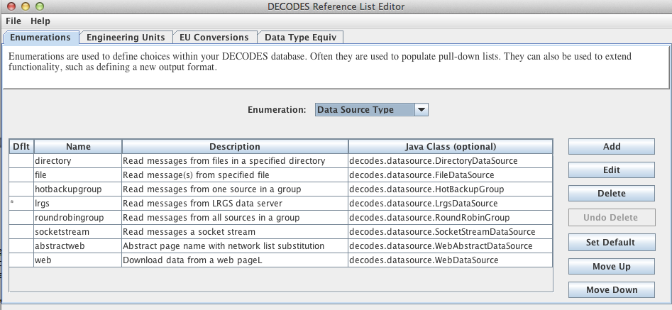
Figure : Required Data Source Enumeration Records for Web Data Sources.
Now as an example, we will be downloading data from the SNOTEL web site. In the Database Editor (dbedit), create a new data source as shown in Figure 3. We set OneMessageFile to true because each page we download has data for a single station and thus should be considered a single message. Since the page has no parsable header, we also set header to “noheader”. The Abstract URL we entered is:
http://www.wcc.nrcs.usda.gov/reportGenerator/view_csv/customSingleStationReport%2Cmetric/hourly/${MEDIUMID}%3AMT%3ASNTL|id%3D%22%22|name/-167%2C0/WTEQ%3A%3Avalue%2CSNWD%3A%3Avalue%2CPREC%3A%3Avalue%2CTOBS%3A%3Avalue
Note that it has the variable ${MEDIUMID} in the middle. When we run the routing spec, this will be replaced by the values in the network list we supply.
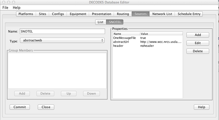
Figure : Example of Abstract URL Data Source.
The routing spec that uses this data source is shown in Figure 4. Note the network list that is assigned. The code will iterate over the platforms in the network list and evaluate the URL for each one. It will then download the web page and parse the entire page as a single DCP message with no header.
Figure 5 shows the network list. Note the numeric Transport (medium) IDs 307, 469, etc. These will be substituted into the abstract URL. Thus the first URL constructed will be:
http://www.wcc.nrcs.usda.gov/reportGenerator/view_csv/customSingleStationReport%2Cmetric/hourly/307%3AMT%3ASNTL|id%3D%22%22|name/-167%2C0/WTEQ%3A%3Avalue%2CSNWD%3A%3Avalue%2CPREC%3A%3Avalue%2CTOBS%3A%3Avalue
The resulting report is shown in Figure 6.
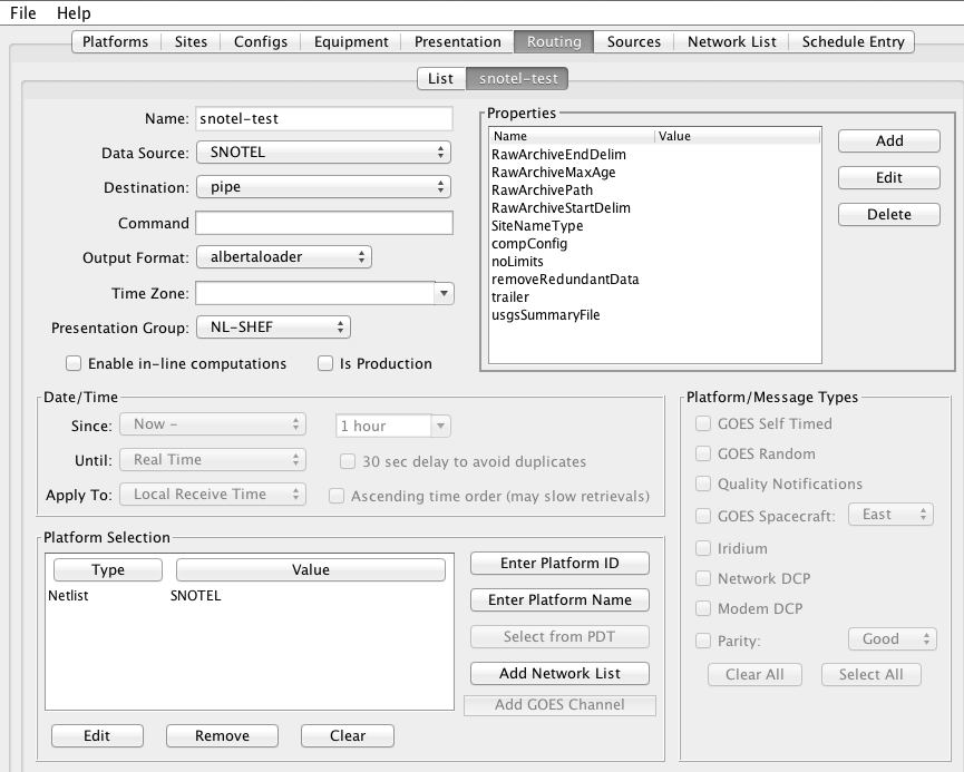
Figure : Routing Spec that uses an Abstract Web Data Source
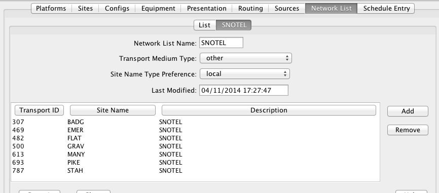
Figure : SNOTEL Network List used by Abstract Web Data Source.
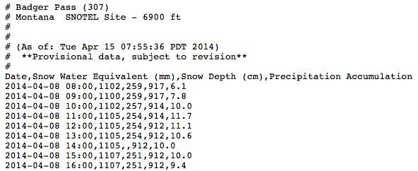
Figure : Snotel Report Downloaded from the Web
FTP Data Source
The FTP Data Source was added in the OpenDCS 6.1 release. If you installed a previous version and then upgraded to 6.1, you may need to manually add the Enumeration record for FTP Data Source.
To do this, run “rledit” and …
On the Enumerations tab, select Enumeration “Data Source Type”
Make sure an entry exists with name “ftp”. If not, hit Add and fill out the form as shown in Figure 7. Be sure to type the Java Class Name exactly as shown. Capitalization matters:
decodes.datasource.FtpDataSource
Hit File – Save to DB.
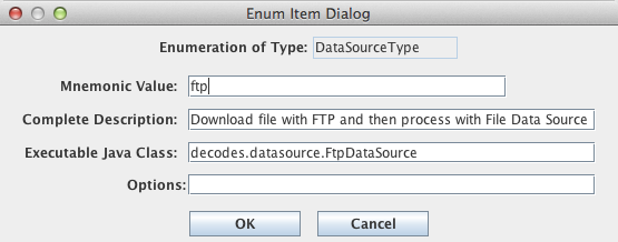
Figure : Form for Adding FTP Data Source in Reference List Editor (rledit).
Now you can enter the DECODES Database Editor and create a Data Source record with type “ftp”. The FTP Data Source can accept the following properties:
Name |
ValueType |
Description |
host |
Ho stname or IP Addr |
Hostname or IP Address of the FTP Server |
port |
I nteger |
Default = 21. FTP Port number on server. |
username |
String |
Username to use when connecting to FTP server |
password |
Pa ssword |
Password to use when connecting to FTP server |
remoteDir |
Dir ectory |
Default = empty string, meaning that the file is at the root on the FTP server. Specify remote directory on server where the file is located. |
localDir |
Dir ectory |
Local directory in which to save the file. If not specified, it defaults to $DCSTOOL_USERDIR/tmp. |
filenames |
String |
A space-separated list of file names to download from the remote directory. Note the ‘s’ on the end of the property name. This property is required. |
xferMode |
Enum |
Default = Binary. Set to ASCII to have FTP do carriage return/linefeed processing. This is not normally needed for DCP messages stored in an FTP file. |
del eteFromServer |
B oolean |
Default = false. Set to true to attempt to delete the file from the server after retrieval. This may be disallowed by the server. If an error occurs, it will not abort processing of the file. |
ftpActiveMode |
B oolean |
Default=false. For security reasons, most public FTP servers operate in Passive mode. |
O neMessageFile |
B oolean |
Default=false. If the entire file is to be treated as a message, set this to true. |
N ameIsMediumId |
B oolean |
Default=false. Usually used in conjunction with OneMessageFile=true. This property, if true, causes the file name to be taken as the medium ID for the purpose of linking it to a platform. |
In addition to these properties, all of the properties specified in section 2.2 above for File Data Source are also accepted. After downloading, the local copy will be processed as if it were a File Data Source.
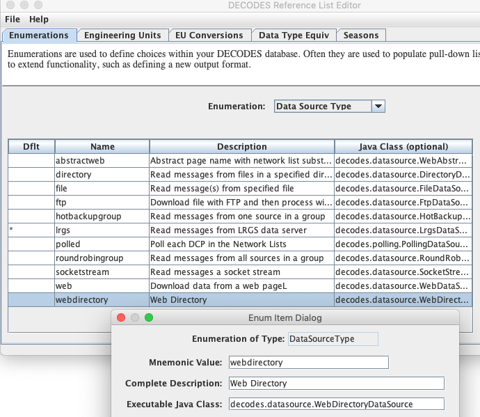
Web Directory Data Source
Web Directory Data Source was designed for the Meteorological Service of Canada (MSC) depot of bulletins containing observation and forecast data. This can be found at:
http://dd.weather.gc.ca/bulletins/
The service provides a directory tree that can be traversed to find the data you’re interested in. DECODES must construct an URL containing a directory. It must then traverse the files in that directory and read the files referenced therein.
For example, the URL contains a directory of file names:
http://dd.weather.gc.ca/bulletins/alphanumeric/20190319/SM/CWAO/11/
Warning
At time of document update These link are not working as the given dates are now too old. Follow the “bulletins” link above to find actual data.
The directory contains a date (20190319) and an hour number (11). Time Zone is always UTC.
The directory contains several file names:
SMCN01_CWAO_191200__71092_38380 2019-03-19 11:58 96 SMCN01_CWAO_191200__71094_36632 2019-03-19 11:59 96 SMCN03_CWAO_191200__71467_58240 2019-03-19 11:59 114 SMCN08_CWAO_191200__71911_46002 2019-03-19 11:59 96 SMCN09_CWAO_191200__71948_12651 2019-03-19 11:58 96
The file names contain a time stamp (191200) which means day 19 (of March), at time 12:00, again in UTC. The file names also contain a numeric station identifier (71092, 71094, etc.)
Note that the date/time and the field numeric field (a check sum) cannot be predicted by DECODES. So in order for DECODES to traverse the depot, it must build a directory name, read the filenames therein, scan for station IDs it is interested in, and then open these files.
The files then contain METAR data:
SMCN03 CWAO 191200
AAXX 19124
71467 46/// /1620 11126 21136 39917 40032 56005 6///1
333 11140 21157 4/023 7////=
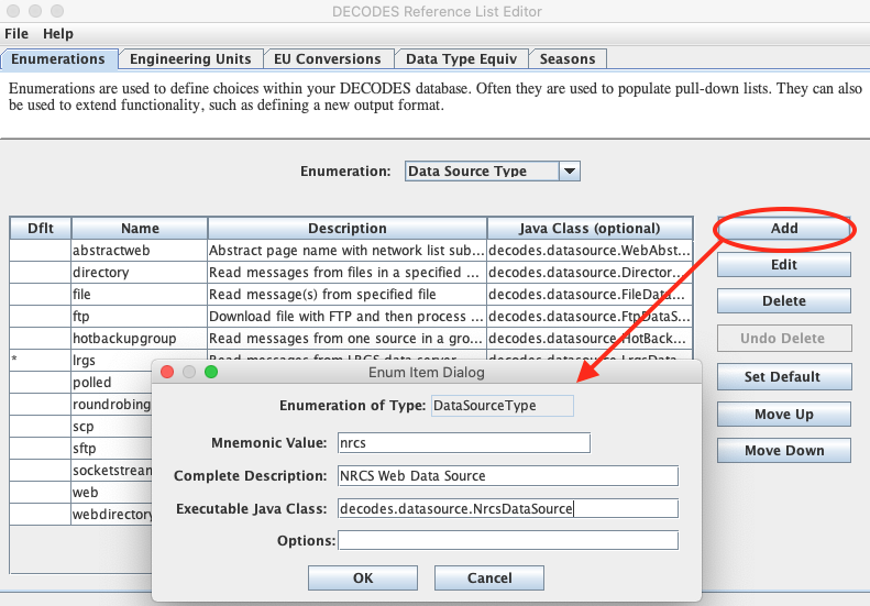
If you have upgraded from a previous version of OpenDCS (prior to 6.6), then you may not have the Data Source Type for Web Directory in your database. Start the Reference List Editor (command “rledit”). Click on the Enumerations tab. Select the Data Source Type enumeration. Click the Add button to the right of the list and fill out the form as shown below.
Be careful to enter the Executable Java Class exactly as shown:
decodes.datasource.WebDirectoryDataSource
Using the SINCE and UNTIL time of the routing spec, DECODES will construct directory names within the time range. It will then read the files therein and attempt to match the IDs in the file name to an ID in a network list assigned to the routing spec.
Properties used by the Data Source include:
Property Name |
Default |
Description |
|---|---|---|
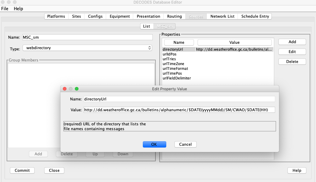
directoryUrl |
none - required |
A template for constructing the directory URL. May contain $DATE(format) specs. |
urlFieldDelimiter |
underscore _ |
Used to parse the file names in the directory. The delimiter separates the different fields of the file name. |
urlTimePos |
3 |
The field number of the time within a file name. In the above examples, “191200” is in the 3rd field of the file name. |
urlIdPos |
5 |
The field number of the platform ID within a file name. In the above examples, the first line has 71091 in the 5th field. Note there are two underscores preceding the station ID, thus the 4th field is empty. |
urlTimeFormat |
ddHHmm |
The format of the time within a file name. See the man page for Java’s SimpleDateFormat for a complete list of possibilities. |
urlTimeZone |
UTC |
The time zone used to construct directory names and to parse the time from file names. |
The following figure shows a DECODES data source record using Web Directory. In most of the properties, the defaults can be used
The following figure shows a DECODES routing spec that uses the MSC_sm data source shown above:
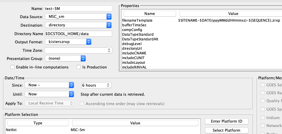
This routing spec will construct directory URLs for “now – 6 hours” through “now”. It will read the directories to discover what files are available. The files with an ID contained in the networklist “MSC-Sm” will be processed. Other files will be ignored.
Output files will be formatted into Kisters XRZP files and given the name shown: The Site name, a date/time stamp, and a sequence number with an extension “.zrxp”. Running this routing spec with the command:
rs –d1 MSC-sm
… resulted in several files in ZRXP format like the following:
71078-20190319080000-24.zxrp
71141-20190319080000-22.zxrp
71854-20190319080000-11.zxrp
71876-20190319080000-30.zxrp
71079-20190319080000-1.zxrp
NOTE: If you want to download the raw files in METAR format, change Output Format to “raw”.
SCP Data Source
SCP Data Source can download files from an SCP (Secure Copy) server and the process the file through DECODES.
If you have updated from an earlier release, you may not have the “scp” data source type in your database. If not, start the Reference List Editor with the “rledit” command and:
On the Enumerations Tab select the “Data Source Type” enumeration.
If “scp” is not in the list, add it with the following values:
Mnemonic Value: scp
Description: Download via SCP and process file
Executable Java Class: decodes.datasource.ScpDataSource
Make sure that the executable class is entered exactly as shown above. Then click File – Save to Db.
The SCP Data Source accepts the following properties, which may be set either in the Data Source record or in the Routing Spec record:
Property Name |
Default |
Description |
|---|---|---|
host |
none - required |
Host name or IP address of the SCP server. |
port |
22 |
Set only if your SCP server uses a non standard port. |
username |
none - required |
User name with which to connect to the SCP server. |
password |
none – required |
Password with which to connect to the SCP server. |
remoteDir |
(default dir) |
If the files you want to download are not in the HOME directory on the server, set this variable. |
localDir |
current dir |
Download the files into this directory prior to processing. If not set, files are downloaded to the current directory. |
filenames |
none – required |
A space-separated list of files to download |
Files are downloaded from the SCP server into the specified “localDir” directory. Then they are processed by FileDataSource. Thus, any of the properties for FileDataSource will also be honored here.
SFTP Data Source
SFTP Data Source can download files from an SFTP (Secure-Shell File Transfer Protocol) server and the process the file through DECODES.
If you have updated from an earlier release, you may not have the “sftp” data source type in your database. If not, start the Reference List Editor with the “rledit” command and:
On the Enumerations Tab select the “Data Source Type” enumeration.
If “sftp” is not in the list, add it with the following values:
Mnemonic Value: sftp
Description: Download via SFTP and process file
Executable Java Class: decodes.datasource.SftpDataSource
Make sure that the executable class is entered exactly as shown above. Then click File – Save to Db.
The SFTP Data Source accepts the following properties, which may be set either in the Data Source record or in the Routing Spec record:
Property Name |
Default |
Description |
|---|---|---|
host |
none - required |
Host name or IP address of the SFTP server. |
port |
22 |
Set only if your SFTP server uses a non standard port. |
username |
none - required |
User name with which to connect to the SCP server. |
password |
none – required |
Password with which to connect to the SCP server. |
remoteDir |
(default dir) |
If the files you want to download are not in the HOME directory on the server, set this variable. |
localDir |
current dir |
Download the files into this directory prior to processing. If not set, files are downloaded to the current directory. |
filenames |
none – required |
A space-separated list of files to download. |
deleteFromServer |
false |
Set to true to have file deleted from the server after it is downloaded. |
Files are downloaded from the SFTP server into the specified “localDir” directory. Then they are processed by FileDataSource. Thus, any of the properties for FileDataSource will also be honored here.
NRCS Web Data Source
This module was added for OpenDCS version 6.8 RC02.
The US Department of Agriculture (USDA) Natural Resources Conservation Service (NRCS) has a web based application through which many types of data can be downloaded including, SNOTEL, Reservoir and stream gages, and climate index stations.
The report generator page can be found at:
https://wcc.sc.egov.usda.gov/reportGenerator/
Using this page you can build reports and then download the results in HTML or CSV (Comma Separated Value) format.
The DECODES NRCS Web Data Source uses information in your DECODES database to construct the proper URL to download CSV reports that can be fed into DECODES and thus ingested into your time series database (e.g. CWMS, OpenTSDB, or HDB). Here is an example URL that the code constructs:
The fields shown in red are dynamically added from information in the DECODES database:
hourly This is the report interval. It will retrieve hourly data. This is provided via a routing spec property.
806 This is the Platform’s NRCS Transport Medium taken from a network list provided to the routing spec.
-31,-7 This is the time range in units of the interval provided. In this case from 31 hours ago through 7 hours ago.
BATT,TOBS These are NRCS data types assigned to the sensors in the configuration records in your DECODES database. BATT is Battery Voltage, TOBS is Observed Air Temperature.
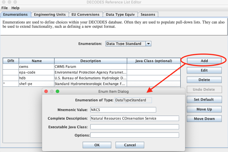
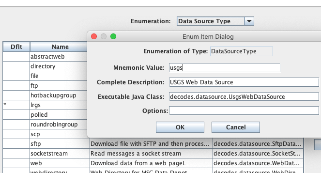
Before using the NRCS Web Data Source you need to set up your database. Start the reference list editor (command ‘rledit’). You need to add two different enumeration values. On the Enumerations Tab, select the ‘Data Source Type’ enumeration. If there is not already an ‘nrcs’ data source, add one by clicking the Add button and filling out the form as shown below.
NOTE: The Executable Java Class must be entered exactly:
decodes.datasource.NrcsDataSource
Next, while still on the Enumerations tab, select the ‘Data Type Standard’ enumeration. If it is not already in the list, click the ‘Add’ button to the right of the list and fill out the form. The Mnemonic value should be exactly ‘NRCS’. The description is optional.
IMPORTANT: Click File – Save to DB before exiting the editor.
Next, import the NRCS presentation group XML file that came with the release. This will bring in all he known NRCS data types. This file can be found in the edit-db/presentation directory under the installation. You can import with the following command:
dbimport $DCSTOOL_HOME/edit-db/presentation/NRCS.xml
Now start the DECODES Database Editor and click the ‘Sources’ tab. Create a new Data Source record. The one shown below is for downloading hourly data:
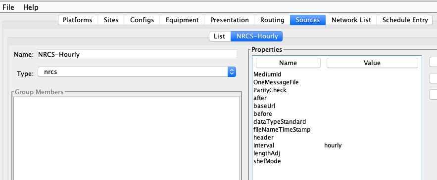
Note the data source type ‘nrcs’ is selected. This links it to the executable java code. The interval is set to ‘hourly’. You can set properties here and/or in the routing spec that uses the data source. If set in both places, the value in the routing spec will override the value set here. The accepted properties are:
Property Name |
Type |
Description & Default Value |
|---|---|---|
baseUrl |
URL String |
This is the base URL for accessing the NRCS reports. The default is shown below. |
interval |
String |
One of hourly, daily, monthly |
dataTypeStandard |
String |
Default=nrcs. If you want to use something other than NRCS data types when building the URL, you can select it here. |
The default baseUrl is:
https://wcc.sc.egov.usda.gov/reportGenerator/view_csv/customMultiTimeSeriesGroupByStationReport/
As an example, we will download Battery Voltage and Observed Air Temperature for two SNOTEL sites:
806 – Sylvan Lake, WY
307 – Badger Pass, MT
The URL for downloading the last 4 hours of data from the 806 site would be:
The report generated by this URL is:
#
# Sylvan Lake (806)
# Wyoming SNOTEL Site - 8420 ft
# Reporting Frequency: Hourly; Date Range: 2020-09-30 00:00 to 2020-09-30 11:00
#
# As of: Sep 30, 2020 11:42:39 AM GMT-08:00
#
Date,Sylvan Lake (806) Battery (volt),Sylvan Lake (806) Air Temperature  Observed (degF)
2020-09-30 00:00,13.01,31
2020-09-30 01:00,12.95,31
2020-09-30 02:00,12.89,30
2020-09-30 03:00,12.84,30
2020-09-30 04:00,12.78,29
2020-09-30 05:00,12.73,29
2020-09-30 06:00,12.69,29
2020-09-30 07:00,12.77,31
2020-09-30 08:00,13.02,41
2020-09-30 09:00,14.28,52
2020-09-30 10:00,14.64,57
2020-09-30 11:00,14.00,61
Note that NRCS gave us all data from midnight on the current day rather than the 4 hours we asked for. Sometimes it imposes a minimum.
Also, the report header (lines starting with #) was actually much longer. We show only the last few lines above.
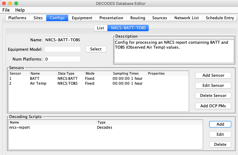
We will start with a DECODES Configuration Record. The snap below shows a config named “NRCS-BATT-TOBS”. It has two sensors with NRCS data types assigned. It has a single Decoding Script called “nrcs-report” that will parse the report shown above.
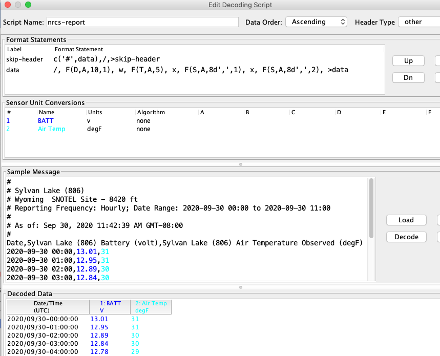
Below is a snap of the decoding script. The script has only two lines.
The “skip-header” line checks for a ‘#’ at the beginning of the line and repeats if there is one. If not it jumps to the line with label “data’.
The data line skips to the start of the next line and then parses the date, time, and two sensor values. It then repeats (by jumping to itself) until the report runs out of data.
The Data Order is given as Ascending, but it really doesn’t matter because each line starts with a time stamp.
The Header Type is ‘other’, meaning that the code doesn’t make any assumptions about the format of a header.
Set the units for each sensor in the middle area.
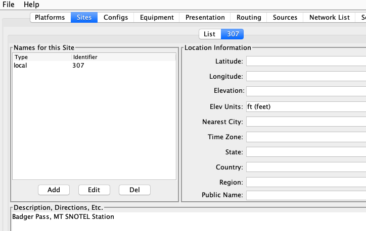
Next create a Site record for each of your stations. Below is a minimal site record for Badger Pass. It uses the SNOTEL identifier as a “local” name. It has a description with the site name. No other information is needed:
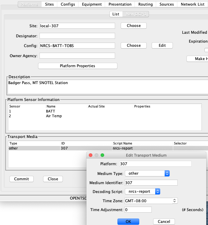
Next, create a Platform record for each station. The snap below shows the platform record for 307. Note the Transport Medium is of type “other”. It has the identifier ‘307’. It also specifies the time zone that will be used when decoding dates & times in the messages.
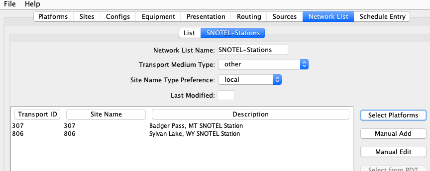
Next create a network list with the two stations.
Give it a unique name. I used ‘SNOTEL-Stations’.
Select Transport Medium Type ‘other’.
Select your site name preference. I used ‘local’.
Click Select Platforms. From the list select both platforms and click OK.
USGS Web Data Source
This module was added for OpenDCS version 6.8 RC02.
The US Geological Survey (USGS) has a web based application through which data can be downloaded for any gauge that the USGS monitors.
The REST data service is described here:
https://waterservices.usgs.gov/rest/IV-Service.html
The DECODES USGS Web Data Source module uses the data service by building URLs for each USGS Site Number in a network list. It uses the routing spec’s since and until times to specify the time range for the data. Here is an example URL:
The fields shown in red are dynamically added from information in the DECODES database:
Before using the USGS Web Data Source you need to set up your database. Start the reference list editor (command ‘rledit’). On the Enumerations Tab, select the ‘Data Source Type’ enumeration. If there is not already a ‘usgs’ data source, add one by clicking the Add button and filling out the form as shown below.
NOTE: The Executable Java Class must be entered exactly:
decodes.datasource.UsgsWebDataSource
Next, while still on the Enumerations tab, select the ‘Data Type Standard’ enumeration. If it is not already in the list, click the ‘Add’ button to the right of the list and fill out the form. The Mnemonic value should be exactly ‘USGS’. The description is optional.
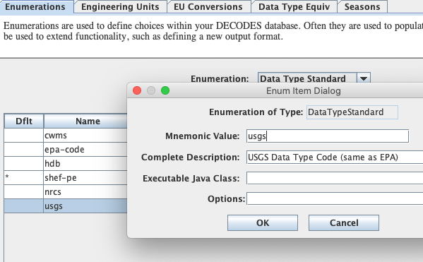
Remember to click File – Save to DB before exiting from rledit.
Now start the DECODES Database Editor and click the ‘Sources’ tab. Create a new Data Source record.
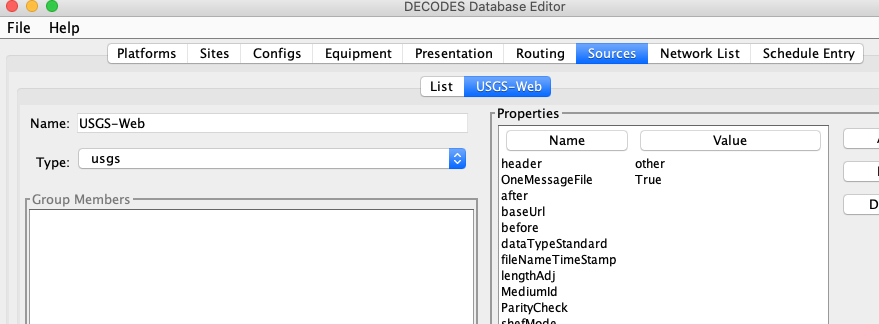
Note the data source type ‘usgs’ is selected. This links it to the executable java code.
We set header to ‘other’ to tell DECODES to not try to process a GOES or Iridium (or any other type of) header.
We set OneMessageFile to true meaning that each URL will return a file that is to be processed as if the entire file constitutes a single message (as opposed to a file with many messages and some kind of delimiters.)
Properties specific to the USGS Web Data Source are:
Property Name |
Type |
Description & Default Value |
|---|---|---|
baseUrl |
URL String |
This is the base URL for accessing the USGS reports. The default is shown below. |
data TypeStandard |
String |
Default=usgs. If you want to use something other than USGS data types when building the URL, you can select it here, but be aware that the USGS web services expects 5-digit USGS parameter codes. |
The default baseUrl is:
https://waterservices.usgs.gov/nwis/iv/?format=rdb&
As an example, we will download Stage and Flow for the following USGS sites:
AGNO – 14372300
CGRO – 14159500
ELKO – 14338000
MLBO - 14337500
The URL for downloading a 4 hour time range of data from the AGNO site would be:
The report generated by this URL is:
# (many more header lines)
# Data provided for site 14372300
# TS_ID Parameter Description
# 117616 00060 Discharge, cubic feet per second
# 117617 00065 Gage height, feet
#
# Data-value qualification codes included in this output:
# P Provisional data subject to revision.
#
agency_cd site_no datetime tz_cd 117616_00060 117616_00060_cd 117617_00065 117617_00065_cd
5s 15s 20d 6s 14n 10s 14n 10s
USGS 14372300 2020-10-11 09:00 PDT 1580 P 2.58 P
USGS 14372300 2020-10-11 09:05 PDT 1580 P 2.58 P
USGS 14372300 2020-10-11 09:10 PDT 1580 P 2.58 P
USGS 14372300 2020-10-11 09:15 PDT 1580 P 2.58 P
. . . many more data lines
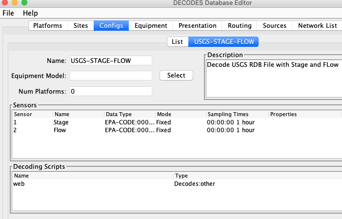
We will start with a DECODES Configuration Record. The snap below shows a config named “USGS-STAGE-FLOW”. It has two sensors Stage and Flow, both with EPA-CODE (same as USGS) data types. It has a single Decoding Script called “web” that will parse the report shown above.
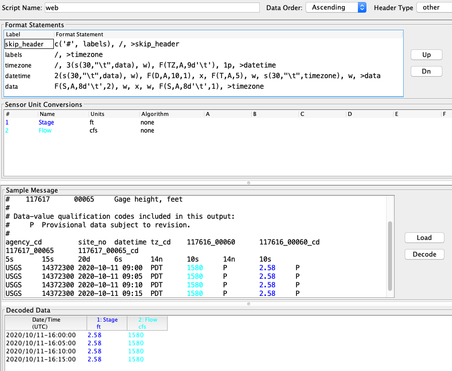
Below is a snap of the decoding with a test message being decoded. This script skips the ‘#’ lines, then skips the 2 column header line, and then parses each data line by grabbing the time zone first, then the date/time, and finally the sensor values.
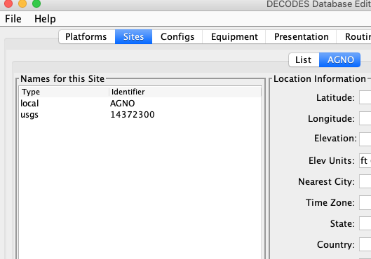
Next create a Site record for each of your stations. Below is a minimal site record for AGNO containing a local name and USGS site number.
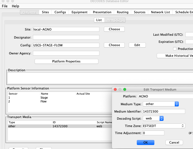
Next, create a Platform record for each station. The snap below shows the platform record for AGNO. Note the Transport Medium is of type “other”. It has the identifier ‘14372300’. It also specifies the time zone that will be used when decoding dates & times in the messages.
After you have created a number of platform records, create a network list containing the transport IDs of the sites you want to process. Make sure to select medium type ‘other’ before clicking the Select Platforms button.
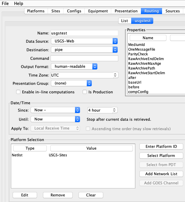
Now you are ready to create a routing spec. The following one retrieves data for the platforms on the “USGS-Sites” network list. It builds URLs to retrieve the last 4 hours worth of data:
An example URL that the data source generated is:
Network Lists
The figure below shows the StPaul Network List being edited.
A network list is a collection of identifiers for a particular transport medium type.
If the transport medium type is “GOES”, the ID is a DCP address (as shown).
If the type is Iridium, the ID is the IMEI number
If the type is data-logger, the ID is the name by which the station identifies itself within the EDL header (this may or may not match a site name).
If the type is Polled-modem, the ID is a telephone number.
You can add or remove sites from the list using the buttons to the right of the list.
You can click in the headers of the list to cause the list to be sorted by Transport ID, Site Name, or Description.
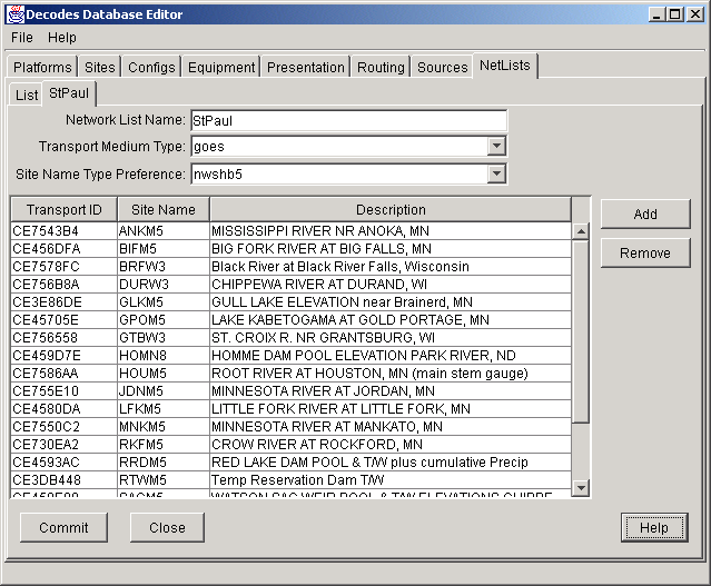
Figure : Network List Edit Panel
Presentation Groups
The Presentation Group Edit Panel is shown in Figure 9.
A Presentation Group determines how data will be formatted for output. This includes:
What engineering units will be used on output.
An optional max and min value for each parameter
Fractional digits (precision) to include in the output
See the ‘HG’ line in the example. This asserts that all SHEF-PE HG values must be in “ft” and have 2 fractional digits.
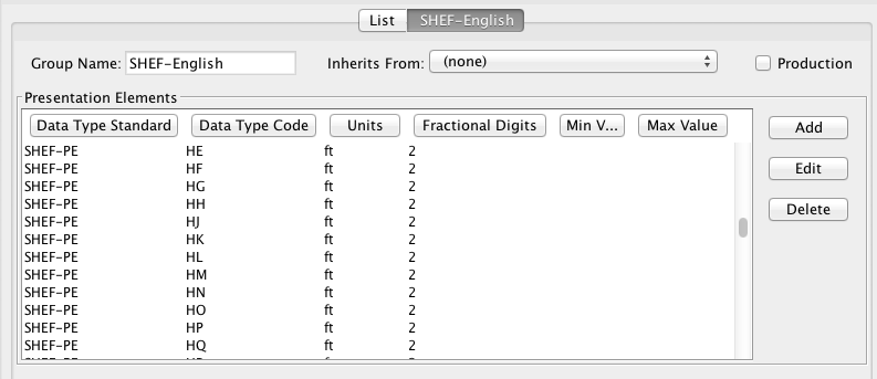
Figure : Presentation Group Edit Panel.
Using a Presentation Group as a Sensor Filter
A presentation group can be used to omit specified data types from your routing spec output. Suppose you want to run a routing spec with no battery voltage output. You can create a presentation group for this purpose as follows:
Create a new Presentation Group called “SensorFilter”.
In the “Inherits From” field, type in SHEF-English.
Click the “Add” button. For data type, specify SHEF-PE with a value of “VB”.
In the Units field, type “omit”.
Now, open your routing spec and select SensorFilter for presentation group.
Routing Specifications
A Routing Specification ties together the above-described entities:
A Routing Spec uses a Data Source to retrieve Raw Data Messages
You Specify the Output Format in the Routing Spec and supply whatever properties the formatter needs.
You supply a destination, or “consumer” for the data. This is normally a file or directory, but can be a database.
You tell the routing Spec what Time Zone to output data in
You tell the routing spec what Presentation Group to use.
You supply search criteria (time ranges, network lists, etc.) that tell the routing spec which data to retrieve.
Figure 10 shows a sample routing spec.
Data is pulled from a hot backup group called “LRGS Group”.
Note the time range: Each time it is run, the spec will retrieve the last hour’s worth of data.
Data is simply ‘piped’ to the standard output when we run the command within a terminal. We could redirect it to a file if we wanted.
Data is placed in the “albertaloader” format in MST. The Presentation Grou “NL-SHEF” is used to determine proper units and precision.
The “goes” network list is used.
In addition to actual lists in your database, you can specify one of two automatic network lists:
<all> is an automatically generated list that includes all platforms defined in your DECODES database.
<production> is an automatically generated list that includes all platforms that have the ‘Production’ checkbox selected.
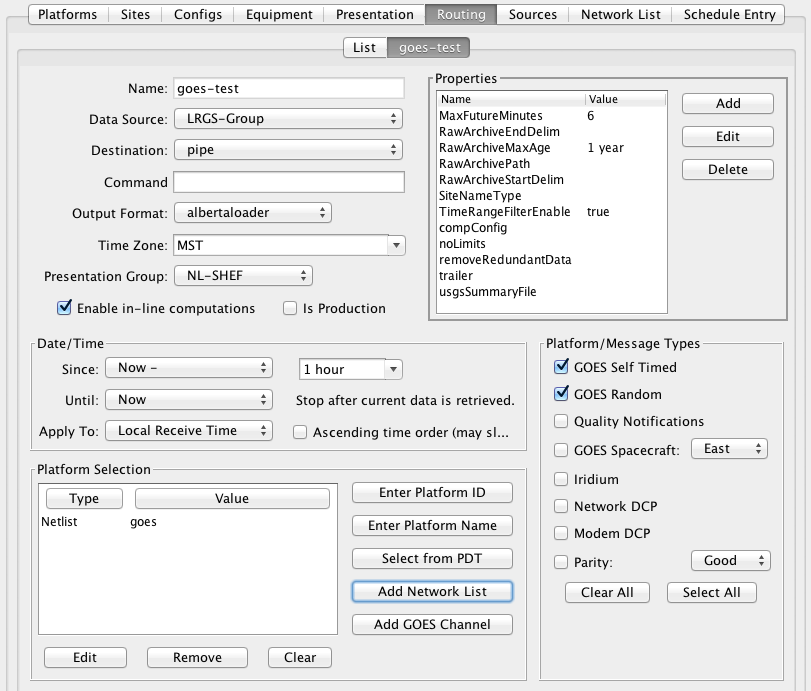
Figure : Routing Spec Edit Panel.
Running a Routing Specification Manually
Type “rs –x” at the command line and you will receive the following help response:
Error: Unknown option -x
Usage: program [-Y <String>] [-P <String>] [-d <Int>] [-l <String>] [-D <String> …] [-m ] [-s <Script-Name> …] [-n <Netlist-Name> …] [-S <String>] [-U <String>] [-o <filename>] [-R ] [-c ] [-C <filename>] [-E <dirname>] [-k <filename>] [-p <property-set> …] [-L <String>] [-M <String>] [-O <String>] <RoutingSpecName>
-Y ‘The log file time-zones’ Default: UTC
-P ‘Name (or path) of DECODES properties file’
-d ‘debug-level’ Default: 0
-l ‘log-file’ Default: routing.log
-D ‘Env-Define’
-m ‘Do NOT apply Sensor min/max limits.’ Default: false
-s ‘ScriptName’
-n ‘Netlist Name’
-S ‘Since Time’
-U ‘Until Time’
-o ‘Status Output File’
-c ‘Enable computations’ Default: false
-C ‘Computation Config File’
-E ‘Explicit Database Location’
-k ‘Optional Lock File’
-p ‘name=value’
-L ‘host:port:user[:password]’
-M ‘Optional Summary File’
-O ‘OfficeID’
‘Routing Spec Name’
Thus to run a routing spec, type ‘rs’ followed by any options you want and finally, the spec name.
rs <options> spec-name
Common Options:
-m Do NOT apply sensor min/max limits (default is to do so).
-n netlist Add the named network list to the routing spec before executing it.
-S since Override “since-time” specified in database routing spec record.
-U until Override “until-time” specified in database routing spec record.
-o filename Set the status monitor output properties file. See below.
-E DatabaseLoc Specify an Explicit XML database location. This allows you to run a routing spec in a database other than your editable or installed database.
-c Enable computations (e.g. USGS RDB File Rating).
-C CompConfigFile Specifies computation configuration file (default is $DECODES_INSTALL_DIR/computations.conf). This can also be set with the ‘compConfig’ Routing Spec Property.
-k lockFile Use specified lock file to ensure only one instance runs and to provide a mechanism to kill the routing spec (by removing the lock file).
-p name=value Adds (or overrides) a routing-spec property.
-L connectSpec Specify LRGS data source on command line, overriding data source specified in database routing spec definition. The ‘connectSpec’ is in the form host:port:user[:password]
Description:
This script starts a Java Virtual Machine running the specified routing spec. All of the parameters that control the action of the routing spec are specified in the database or the DECODES properties file. Hence there are no options to this command.
Examples:
rs Atlanta-lrgs-input Execute routing spec “Atlanta-lrgs-input” from the installed database.
rs -e test Execute routing spec “test” from the editable database.
rs -e -s ST test Execute routing spec “test” from the editable database, but only process messages for ST (self-timed) scripts.
Each routing spec writes trouble-shooting information to a separate log file. The file has the name of the routing spec with a “.log” extension. These files will be placed in the directory specified by the ‘RoutingStatusDir’ value in decodes.properties. If none is defined, the default of $DECODES_INSTALL_DIR/routstat will be used.
Thus look for the log file for routing spec ‘test’ in the file:
$DECODES_INSTALL_DIR/routstat/test.log.
Overriding Time Range from the Command Line
The -S and -U arguments (note, must be capital letters) can be used to override the time range specified in the database. For example, the following runs ‘myspec’ but the since time is replaced by “now - 1 day”:
rs -e -S ‘now - 1 day’ myspec
Note that the string must be enclosed in single quotes so that it is passed as a single argument. Also note that it must be separated from the -S by at least one space.
Status Output File
The routing spec will write its status periodically to a file. This allows you to check on the status of the specs running in the background.
By default, the output file will be called “name.status”, where name is the name of the routing spec. The file will be placed in the directory specified in the decodes.properties file. (Refer back to Error! Reference source not found.).
You can specify a particular file with the –o command line argument. For example, to have the status written to “/tmp/mystat.status”, use the following command line argument:
rs –o /tmp/mystat.status … (other args here) …
If you do not want the spec to write status, include the argument with a value of “-“. As follows:
rs –o - … (other args here) …
Optional Lock File
The –k argument allows you to specify a lock file for this instance of the routing spec. Lock files do two things:
Ensure only one instance with a given lock file can run: If the lock is busy, the routing spec will fail to start.
Provide an easy way to terminate a background routing spec: Simply delete the lock file.
While running, the process will ‘touch’ the lock file every 10 seconds. If the file was deleted, the process will terminate. So allow about 10 seconds after deleting a lock file before starting a new instance.
A lock file is “busy” if it exists and has been touched within the last 20 seconds.
Expanding Environment Variables
Several of the properties listed in the following sections allow embedded environment variables. This is particularly true for file and directory names. The following table list the substitutions that are done:
String |
Replaced with … |
~ |
Current user’s home directory. |
$HOME |
Current user’s home directory. |
$DATE |
Current Date/Time in default format. |
$DATE(format) |
Current Date/Time in user specified format (see below). |
$DECODES_INSTALL_DIR – or – $DCSTOOL_HOME |
The location where DECODES was installed. |
$DCSTOOL_USERDIR |
For multi-user installations, this is the location of the user’s specific configuration. |
$user.dir |
The current working directory. |
The Date/Time format is specified with a string passed to the Java “SimpleDateFormat” class. See Sun’s documentation at the following URL for a description of format options.
http://java.sun.com/j2se/1.5.0/docs/api/java/text/SimpleDateFormat.html
Output Formatters
DECODES supports an ever expanding list of output formats. The list available to you is controlled by the “Output Format” Enumeration in the Reference List Editor. Type “rledit” at the command line. Then on the Enumerations tab select “Output Format”.
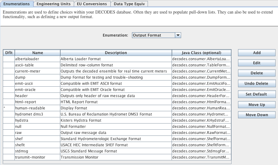
Figure : Reference List Editor - Output Formatter List.
SHEF Output Format
The SHEF Output Formatter can produce either the “.A” or “.E” type lines. Examples are shown in the figures below.
.E is normally used for regular interval data, such as is found in self-timed DCP messages.
.A is normally used for irregular interval data, such as is found in random DCP messages.
The SHEF Formatter honors the following routing-spec properties:
Name |
Value Type |
Default |
Description |
dotAOnly |
True /false |
false |
If true, force output to be .A lines only, even for self-timed (regular interval) data. |
century |
True /false |
false |
SHEF time stamps allow 4 digit or 2 digit years. The default is a 2 digit year. To force the century to be included, add this property set to “true”. |
seconds |
True /false |
true |
Likewise, seconds can be omitted in SHEF time stamps. By default they are included. To force them to be dropped, add a this property with a value of “false”. |
useNesdisId |
True /false |
false |
Normally the default Site Name is used in the SHEF output. To force the output to use the 8 hex-char NESDIS ID, set this to true. |
f ullShefCode |
True /false |
false |
Normally the SHEF output will only include the 2-character physical element (PE) code entered with each sensor. If you want a full 7 digit code constructed by filling out the trailing 5 characters, set this to true. |
defa ultShefCode |
7-char string |
xxIRZZZ |
If “fullShefCode” is set to true, you can control the characters used to fill-out the 7-character code. |
Figure : Example of SHEF .A:
.A BRFW3 011203 GMT+00:00 DH110000 /DUE /HG 38.36 :ft
.A BRFW3 011203 GMT+00:00 DH100000 /DUE /HG 38.35 :ft
.A BRFW3 011203 GMT+00:00 DH090000 /DUE /HG 38.34 :ft
.A BRFW3 011203 GMT+00:00 DH080000 /DUE /HG 38.35 :ft
.A BRFW3 011203 GMT+00:00 DH070000 /DUE /HG 38.35 :ft
.A BRFW3 011203 GMT+00:00 DH060000 /DUE /HG 38.35 :ft
.A BRFW3 011203 GMT+00:00 DH050000 /DUE /HG 38.35 :ft
.A BRFW3 011203 GMT+00:00 DH040000 /DUE /HG 38.35 :ft
.A BRFW3 011203 GMT+00:00 DH110000 /DUS /PC 6.26 :INCH
.A BRFW3 011203 GMT+00:00 DH100000 /DUS /PC 6.26 :INCH
.A BRFW3 011203 GMT+00:00 DH090000 /DUS /PC 6.26 :INCH
.A BRFW3 011203 GMT+00:00 DH080000 /DUS /PC 6.26 :INCH
.A BRFW3 011203 GMT+00:00 DH070000 /DUS /PC 6.26 :INCH
.A BRFW3 011203 GMT+00:00 DH060000 /DUS /PC 6.26 :INCH
.A BRFW3 011203 GMT+00:00 DH050000 /DUS /PC 6.26 :INCH
.A BRFW3 011203 GMT+00:00 DH040000 /DUS /PC 6.26 :INCH
Figure : Example of SHEF .E:
.E SSIM5 020212 GMT DH150000 /DUS /VB/ DIH+1 /14.344 :V
.E LFKM5 020212 GMT DH080000 /DUE /HG/ DIH+1 /2.79/2.79/2.79/2.79/2.79/2.79/2.79/2.79 :ft
.E LFKM5 020212 GMT DH150000 /DUE /VB/ DIH+1 /14.344 :VOLT
.E VRNN8 020212 GMT DH150000 /DUE /VB/ DIH+1 /13.876 :VOLT
.E BRFW3 020212 GMT DH080000 /DUE /PC/ DIH+1 /6.26/6.26/6.26/6.26/6.26/6.26/6.26/6.26 :in
.E BRFW3 020212 GMT DH150000 /DUS /VB/ DIH+1 /14.5 :V
.E DURW3 020212 GMT DH080000 /DUE /HG/ DIH+1 /1.75/1.72/1.63/1.6/1.55/1.49/1.49/1.49 :ft
.E DURW3 020212 GMT DH150000 /DUS /VB/ DIH+1 /13.84 :V
.E HOMN8 020212 GMT DH160000 /DUS /VB/ DIH+1 /14.11 :V
SHEFIT Output Format
SHEFIT is an expanded form of SHEF commonly used by the U.S. Army Corps of Engineers.
Figure : Example of SHEFIT Output Format:
CE459D7E20011203110000 0 0 0 0 0 0 HP RZZ 1055.530 Z -1.00 0 0 0
CE459D7E20011203100000 0 0 0 0 0 0 HP RZZ 1055.530 Z -1.00 0 0 0
CE459D7E20011203090000 0 0 0 0 0 0 HP RZZ 1055.530 Z -1.00 0 0 0
CE459D7E20011203080000 0 0 0 0 0 0 HP RZZ 1055.530 Z -1.00 0 0 0
CE459D7E20011203070000 0 0 0 0 0 0 HP RZZ 1055.530 Z -1.00 0 0 0
CE459D7E20011203060000 0 0 0 0 0 0 HP RZZ 1055.530 Z -1.00 0 0 0
CE459D7E20011203050000 0 0 0 0 0 0 HP RZZ 1055.530 Z -1.00 0 0 0
CE459D7E20011203040000 0 0 0 0 0 0 HP RZZ 1055.530 Z -1.00 0 0 0
CE459D7E20011203030000 0 0 0 0 0 0 HP RZZ 1055.530 Z -1.00 0 0 0
CE459D7E20011203020000 0 0 0 0 0 0 HP RZZ 1055.520 Z -1.00 0 0 0
CE459D7E20011203010000 0 0 0 0 0 0 HP RZZ 1055.520 Z -1.00 0 0 0
CE459D7E20011203000000 0 0 0 0 0 0 HP RZZ 1055.520 Z -1.00 0 0 0
CE459D7E20011203110000 0 0 0 0 0 0 PC RZZ .000 Z -1.00 0 0 0
CE459D7E20011203100000 0 0 0 0 0 0 PC RZZ .000 Z -1.00 0 0 0
CE459D7E20011203090000 0 0 0 0 0 0 PC RZZ .000 Z -1.00 0 0 0
CE459D7E20011203080000 0 0 0 0 0 0 PC RZZ .000 Z -1.00 0 0 0
CE459D7E20011203070000 0 0 0 0 0 0 PC RZZ .000 Z -1.00 0 0 0
CE459D7E20011203060000 0 0 0 0 0 0 PC RZZ .000 Z -1.00 0 0 0
As of OpenDCS 6.1 RC17, SHEFIT formatter allows a single property:
Name |
Value Type |
D efault |
Description |
sit eNameType |
Valid name type |
(empty) |
By default, SHEFIT puts the NESDIS DCP Address in the first 8 characters of each line. Set the ‘siteNameType’ property to have the first 8 characters assigned from the site name of the specified type. Names will be truncated to 8 characters if longer, or padded with spaces if less than 8 characters. |
Human Readable Output Format
The Human Readable Formatter is designed, well, for humans. It displays the message data in the simple table format shown below. It also honors the following properties:
Name |
Value Type |
D efault |
Description |
dis playEmpty |
Tru e/false |
false |
Normally, empty columns will be omitted. Add this property and set it to true to cause a column to be displayed even for sensors that have no data. |
delimiter |
String |
“ | “ |
String to delimit the columns. |
datatype |
String |
SHEF-PE |
The data type standard to display in the header |
d ateformat |
String |
See man page on SimpleDateFormat. This string specifies the format of the date/time stamps. |
Message for Platform NWSHB5-HOMN8
Figure : Example of Human Readable Output Format:
| elev | PC | battery |
| HP | PC | VB |
| ft | in | V |
12/03/2001 00:00:00 | 1055.53 | 0.0 | |
12/03/2001 01:00:00 | 1055.53 | 0.0 | |
12/03/2001 02:00:00 | 1055.53 | 0.0 | |
12/03/2001 03:00:00 | 1055.53 | 0.0 | |
12/03/2001 04:00:00 | 1055.53 | 0.0 | |
12/03/2001 05:00:00 | 1055.53 | 0.0 | |
12/03/2001 06:00:00 | 1055.53 | 0.0 | |
12/03/2001 07:00:00 | 1055.53 | 0.0 | |
12/03/2001 08:00:00 | 1055.53 | 0.0 | |
12/03/2001 09:00:00 | 1055.52 | 0.0 | |
12/03/2001 10:00:00 | 1055.52 | 0.0 | |
12/03/2001 11:00:00 | 1055.52 | 0.0 | 13.876 |
Message for Platform NWSHB5-WTSM5:
| pool | tail | battery |
| HP | HT | VB |
| ft | ft | VOLT |
12/03/2001 00:00:00 | 900.0 | 935.5 | |
12/03/2001 01:00:00 | 900.0 | 935.49 | |
12/03/2001 02:00:00 | 900.0 | 935.5 | |
12/03/2001 03:00:00 | 900.0 | 935.51 | |
12/03/2001 04:00:00 | 900.0 | 935.54 | |
12/03/2001 05:00:00 | 900.0 | 935.61 | |
12/03/2001 06:00:00 | 900.0 | 935.65 | |
12/03/2001 07:00:00 | 900.0 | 935.67 | |
12/03/2001 08:00:00 | 900.0 | 935.67 | |
12/03/2001 09:00:00 | 900.0 | 935.65 | |
12/03/2001 10:00:00 | 900.0 | 935.64 | |
12/03/2001 11:00:00 | 900.0 | 935.61 | 12.004 |
EMIT-ASCII Format
If the routing spec contains a string property called ‘delimiter’, this will be used to delimit between columns. The default is a single space.
The EMIT-ASCII formatter produces an output that is compatible with the old EMIT program when “ASCII” was selected as the output format. This format has 12 blank-delimited fields as follows:
Hex DCP Address
EPA Sensor Code (0 if none is assigned)
Sensor Number
Time Stamp in the format: YYDDD/HH:MM:SS
Sample Value (formatted as specified by Presentation Group)
‘I’ if this is a self-timed message (meaning interval data); or ‘R’ if this is a random message.
DCP Name (the preferred site name as specified by your properties file is used)
Sensor Name
SHEF Code (or ‘XX’ if none is specified)
Recording interval for this sensor (in seconds)
‘I’
Engineering Units
Following all sample data, a single line with ‘ZZZZ’ is printed. Error! Reference source not found. shows a single message in EMIT-ASCII format.
If you have used station or sensor names that have embedded spaces, you can use an additional property ‘useQuotes’ set to TRUE. This will cause the station and sensor names to be enclosed in single quotes.
Example of EMIT-ASCII format:
CE459D7E 0 1 01337/11:00:00 1055.53 I HOMN8 elev HP 3600 I ft
CE459D7E 0 1 01337/10:00:00 1055.53 I HOMN8 elev HP 3600 I ft
CE459D7E 0 1 01337/09:00:00 1055.53 I HOMN8 elev HP 3600 I ft
CE459D7E 0 1 01337/08:00:00 1055.53 I HOMN8 elev HP 3600 I ft
CE459D7E 0 1 01337/07:00:00 1055.53 I HOMN8 elev HP 3600 I ft
CE459D7E 0 1 01337/06:00:00 1055.53 I HOMN8 elev HP 3600 I ft
CE459D7E 0 1 01337/05:00:00 1055.53 I HOMN8 elev HP 3600 I ft
CE459D7E 0 1 01337/04:00:00 1055.53 I HOMN8 elev HP 3600 I ft
CE459D7E 0 1 01337/03:00:00 1055.53 I HOMN8 elev HP 3600 I ft
CE459D7E 0 1 01337/02:00:00 1055.52 I HOMN8 elev HP 3600 I ft
CE459D7E 0 1 01337/01:00:00 1055.52 I HOMN8 elev HP 3600 I ft
CE459D7E 0 1 01337/00:00:00 1055.52 I HOMN8 elev HP 3600 I ft
CE459D7E 00045 2 01337/11:00:00 0.0 I HOMN8 PC PC 3600 I in
CE459D7E 00045 2 01337/10:00:00 0.0 I HOMN8 PC PC 3600 I in
CE459D7E 00045 2 01337/09:00:00 0.0 I HOMN8 PC PC 3600 I in
CE459D7E 00045 2 01337/08:00:00 0.0 I HOMN8 PC PC 3600 I in
CE459D7E 00045 2 01337/07:00:00 0.0 I HOMN8 PC PC 3600 I in
CE459D7E 00045 2 01337/06:00:00 0.0 I HOMN8 PC PC 3600 I in
CE459D7E 00045 2 01337/05:00:00 0.0 I HOMN8 PC PC 3600 I in
CE459D7E 00045 2 01337/04:00:00 0.0 I HOMN8 PC PC 3600 I in
CE459D7E 00045 2 01337/03:00:00 0.0 I HOMN8 PC PC 3600 I in
CE459D7E 00045 2 01337/02:00:00 0.0 I HOMN8 PC PC 3600 I in
CE459D7E 00045 2 01337/01:00:00 0.0 I HOMN8 PC PC 3600 I in
CE459D7E 00045 2 01337/00:00:00 0.0 I HOMN8 PC PC 3600 I in
CE459D7E 70969 3 01337/11:00:00 13.876 I HOMN8 battery VB 3600 I V
ZZZZ
EMIT-Oracle Format
This format is similar to EMIT-ASCII but more compact. It was originally designed to input data into an Oracle database, hence the name. It is, however, a generally useful format in its own right, very easy to parse with a computer program.
The ‘delimiter’ property is supported in the same way as for EMIT-ASCII.
The EMIT-ORACLE formatter produces an output that is compatible with the old EMIT program when “ORACLE” was selected as the output format. This format has 7 blank-delimited fields as follows:
Hex DCP Address
SHEF Code (or ‘XX’ if none is specified)
Sensor Number
Time Stamp in the format: YYDDD/HH:MM:SS
Sample Value (formatted as specified by Presentation Group)
‘I’ if this is a self-timed message (meaning interval data); or ‘R’ if this is a random message.
Engineering Units
Following all sample data, a single line with ‘ZZZZ’ is printed. The following figure shows a single message in EMIT-Oracle format.
Figure : Example of EMIT Oracle Format:
CE459D7E HP 1 01337/11:00:00 1055.53 I ft
CE459D7E PC 2 01337/11:00:00 0.0 I in
CE459D7E VB 3 01337/11:00:00 13.876 I V
ZZZZ
EMIT-Oracle Formatter will accept the following properties:
Name |
Default |
Description |
|---|---|---|
delimiter |
(space) |
Separator between columns. |
siteNameType |
(none) |
Default is to use the GOES DCP address, as shown in the example above. To substitute for a site name, enter the type as a property. You can enter multiple site name types separated by commas to show a preference order. For example “CWMS,NWSHB5” would mean to use the CWMS name if one is available. If not try the NWSHB5 name. If neither exists it will use whatever name for the site that it has. |
sitePrefix |
(none) |
A constant string to be placed at the beginning of the site name. |
dateFormat |
yyDDD/HH:mm:ss |
This is a Java SimpleDateFormat string (google that for details) that specifies how the program will format date/time values. Example: “MM/dd/yyyy,HH:mm:ss,z” would print a value like: 04/19/2016,12:15:00,UTC |
dataType |
SHEF-PE |
Specifies the data type to be included in the 2nd column. |
justify |
true |
By default, the formatter will pad with blanks to line up the columns. Set to false to disable this. |
addMsgDelim |
true |
Include line ZZZZ meaning message delimiter |
Example, to print data like this:
GOSO,Stage-Tailwater,1,04/13/2017 20:15:00,11.25,I,ft
Set the following properites:
delimiter = , (i.e. a single comma)
siteNameType = Local (assuming GOSO is an Local name type)
dateFormat = MM/dd/YYYY HH:mm:ss
dataType = CWMS
justify=false
addMsgDelim=false
Dump Formatter
DumpFormatter is useful for testing and trouble-shooting. It dumps the raw message, performance measurements, and decoded data to an output interface. The following figure shows an example of this format.
Start of message for platform NWSHB5-HOMN8
Time Stamp: 12/02/2001 16:08:11
Raw Data:
CE459D7E01336210811G44-4NN031E9200077B1HAvq@@@Avq@@@Avq@@@Avq@@@Avq@@@Avq@@@Avq@@@Avq@@@Avq@@@Avp@@@Avp@@@Avp@@@N
Performance Measurements:
DcpAddress=CE459D7E
Spacecraft=E
UplinkCarrier=92
Channel=31
SignalStrength=44
Length=77
ModulationIndex=N
Quality=N
Time=12/02/2001 21:08:11
FailureCode=G
FrequencyOffset=-4
Decoded Data:
Sensor 1: elev, EU=ft(feet), DataType=SHEF-PE:HP
Begin=12/02/2001 16:53:33, End=12/03/2001 06:00:00
Number of Samples=12
Sample[0]=12/03/2001 06:00:00: 1055.53 ' 1055.53'
Sample[1]=12/03/2001 05:00:00: 1055.53 ' 1055.53'
Sample[2]=12/03/2001 04:00:00: 1055.53 ' 1055.53'
Sample[3]=12/03/2001 03:00:00: 1055.53 ' 1055.53'
Sample[4]=12/03/2001 02:00:00: 1055.53 ' 1055.53'
Sample[5]=12/03/2001 01:00:00: 1055.53 ' 1055.53'
Sample[6]=12/03/2001 00:00:00: 1055.53 ' 1055.53'
Sample[7]=12/02/2001 23:00:00: 1055.53 ' 1055.53'
Sample[8]=12/02/2001 22:00:00: 1055.53 ' 1055.53'
Sample[9]=12/02/2001 21:00:00: 1055.52 ' 1055.52'
Sample[10]=12/02/2001 20:00:00: 1055.52 ' 1055.52'
Sample[11]=12/02/2001 19:00:00: 1055.52 ' 1055.52'

Sensor 2: PC, EU=in(inches), DataType=SHEF-PE:PC
Begin=12/02/2001 16:53:33, End=12/03/2001 06:00:00
Number of Samples=12
Sample[0]=12/03/2001 06:00:00: 0 '0.0 '
Sample[1]=12/03/2001 05:00:00: 0 '0.0 '
Sample[2]=12/03/2001 04:00:00: 0 '0.0 '
Sample[3]=12/03/2001 03:00:00: 0 '0.0 '
Sample[4]=12/03/2001 02:00:00: 0 '0.0 '
Sample[5]=12/03/2001 01:00:00: 0 '0.0 '
Sample[6]=12/03/2001 00:00:00: 0 '0.0 '
Sample[7]=12/02/2001 23:00:00: 0 '0.0 '
Sample[8]=12/02/2001 22:00:00: 0 '0.0 '
Sample[9]=12/02/2001 21:00:00: 0 '0.0 '
Sample[10]=12/02/2001 20:00:00: 0 '0.0 '
Sample[11]=12/02/2001 19:00:00: 0 '0.0 '

Sensor 3: battery, EU=V(volts), DataType=SHEF-PE:VB
Begin=12/02/2001 16:53:33, End=12/03/2001 06:00:00
Number of Samples=1
Sample[0]=12/03/2001 06:00:00: 13.876 ' 13.876
Figure : Example of Dump Output Format
Transmit Monitor Formatter
The Transmit Monitor format provides a log of transmission quality measurements in an easy-to-use row column format. The following columns are used by default:
Message Time Stamp in the form MM/DD/YYYY-HH:MM:SS
DCP Address (Transport Medium ID)
Site Name
Failure Code
SignalStrength
Message Length
GOES Channel Number
Frequency Offset
Modulation Index
Battery Voltage
An example of the default format is shown below:
10/30/2002-20:03:33 CE7718EE 03324500 G 50 209 23 -4 N N 14.83
10/30/2002-20:16:50 CE77835E 03360000 G 50 97 23 -5 N N 13.88
10/30/2002-20:29:25 CE777D08 03327500 G 50 161 23 -2 N N 14.37
10/30/2002-21:03:11 CE14B3F8 03324000 G 50 145 179 0 H N 13.70
10/30/2002-21:07:22 CE14C568 03275000 G 50 113 179 -1 N N 13.74
10/30/2002-22:21:29 CE6D361C 03335500 G 49 113 41 -4 N F 14.12
10/31/2002-00:03:33 CE7718EE 03324500 G 49 209 23 -3 N N 14.72
10/31/2002-00:05:30 CE772D74 03375500 G 49 105 23 -3 N N 13.3
10/31/2002-00:06:27 CE7730D0 03276000 G 49 145 23 2 N N 14.8
10/31/2002-00:16:50 CE77835E 03360000 G 49 97 23 -5 N N 14.23
10/31/2002-00:29:25 CE777D08 03327500 G 50 161 23 -2 N N 13.99
10/31/2002-01:03:11 CE14B3F8 03324000 G 50 145 179 0 H N 13.70
10/31/2002-02:21:29 CE6D361C 03335500 G 50 113 41 -4 N N 14.11
10/31/2002-04:16:50 CE77835E 03360000 G 49 97 23 -5 N N 13.88
10/31/2002-04:29:25 CE777D08 03327500 G 49 161 23 -2 N N 13.79
10/31/2002-05:03:11 CE14B3F8 03324000 G 49 145 179 0 H N 13.70
10/31/2002-05:05:41 CE14D61E 03357500 G 50 145 179 -9 N N 14.70
10/31/2002-05:07:22 CE14C568 03275000 G 50 113 179 -1 N N 13.57
10/31/2002-06:21:29 CE6D361C 03335500 G 50 113 41 -4 N N 14.17
Figure : Example of Transmit Monitor Format
You can control the contents of the transmit monitor format by adding properties to the routing specification:
The string property “delimiter” has a default value of a single space character. This is used to separate columns in the output. To ingest this data into a SQL database, for example, you may wish to use a comma as a delimiter.
The Boolean property “justify” defaults to ‘true’. This causes each column to be either right or left justified within the column width. The example above shows justified columns.
The string property “columns” is a blank or comma-separated list of columns that you wish to see in the output. Table 9‑2 shows the column names that can be included in this string. The default value for the string is:
“time id name FailureCode SignalStrength Length Channel FrequencyOffset ModulationIndex Quality batt”
ColumnName |
Description |
time |
Message time stamp in the format MM/DD/YYYY-HH:MM:SS |
id |
Transport ID (i.e. DCP address for GOES messages) |
name |
Site name |
FailureCode |
1-character code for GOES messages: ‘G’ means good message, ‘?’ means parity errors. |
Length |
Length of the raw message in bytes |
Channel |
GOES Channel number |
FrequencyOffset |
A sign plus a digit, taken from the DOMSAT message header, this indicates the frequency offset of the raw message, as reported by DAPS. The digit indicates the amount of the offset in units of 50Hz. |
ModulationIndex |
‘N’ for Normal, ‘L’ for Low, ‘H’ for High |
Quality |
‘N’ (normal) = Error rate betterh than 10-6, ‘F’ (fair) = Error rate between 10-4 and 10-6 ’P’ (poor) = Error rate worse than 10-4 |
SignalStrength |
in dB. |
Spacecraft |
‘E’ (East), or ‘W’ (West) |
UplinkCarrier |
Uplink Carrier Status (not implemented in DAPS-I) |
batt |
Battery voltage if available. The most recent sample contained in the message will be printed. This looks for a sensor with a name that starts with “batt”. If none found it looks for any sensor with a datatype equivalent to VB. |
The string property “colwidths” is used to control the width and justification of each column. It should be a blank or comma-separated list of numbers, one for each column. A positive number means right-justified. A negative number means left-justified. The default value of this property is:
19, 8, 10, 1, 5, 3, 2, 2, 2, 5
Example: Cause the formatter to print a comma-separated list of messages. For each message we only want the time, DCP Address, and battery voltage.
Add the following properties to the routing spec:
delimiter = , (i.e. a single comma)
justify = false
columns = time id batt
colwidths = 19, 8, 7
Raw Formatter
This formatter simply outputs a raw message (that is un-decoded).
It supports the following Boolean property:
noStatusMessages – value=’true’ or ‘false’. If true, then the formatter will skip DAPS status messages.
Use the consumer’s properties to place delimiters before or after each message. For example, if you’re using the ‘pipe’ consumer, the properties ‘consumerBefore’ and ‘consumerAfter’ will place special strings before and after each message in the output.
Hydstra Formatter
This format is used for ingesting data into the ‘Hydstra’ software from Kisters. Specifically, it is for use with the SVRIMP utility.
A sample of the Hydstra Format is shown below:
HNKM2 , 0001.00, 20091201193000, 3.96000, 1, 1, 0
HNKM2 , 0001.00, 20091201194500, 3.96000, 1, 1, 0
HNKM2 , 0001.00, 20091201200000, 3.96000, 1, 1, 0
HNKM2 , 0001.00, 20091201201500, 3.96000, 1, 1, 0
HNKM2 , 0001.00, 20091201203000, 3.96000, 1, 1, 0
This is a comma-separated-value format with (mostly) fixed-length fields as follows:
SSSSSSSSSSSSSSS, FFFF.FF, YYYYMMDDHHIIEE, VVVVVV.VVV, QQQ, RR, GGGG
Where …
SSSSSSSSSSSSSSS is the station name padded to 15 characters. DECODES will look for a name with type “hydstra”. If none exists, it will use the default name for the station.
FFFF.FF is the Hydstra data type code for the sensor, padded to 7 characters. It is up to you to enter the data type code for each sensor in the required 4.2 format.
YYYYMMDDHHIIEE is the time-stamp for the value. This will be in whatever time-zone you are using in the retrieval process.
VVVVV.VVV is the data value. This is the only field which is not fixed length. This field will be formatted according to whatever presentation group you are using in the retrieval process. If you require it to be fixed length, we suggest that you prepare a presentation group called ‘hydstra’ that sets the required format for all possible hydstra data types, and then apply this group when you run a retrieval process.
QQQ is the ‘hydstra’ quality code. DECODES sets this to a constant 1 (padded to 3 characters).
RR is the Hydstra data-trans code. DECODES will default this to a constant 1. If you need this to be something else, add a sensor property call ‘HydstraTransCode’ with whatever value you want.
GGGG is the maxgap between points. DECODES will default this to 0, meaning “don’t care”. If you need this to be something else, add a sensor property called ‘HydstraMaxGap’ with whatever value you want (limit 4 characters).
You may need to create an enumeration entry for the hydstra data type code. Start the reference list editor (rledit), click the Enumerations tab, then select the Data Type Standard enumeration. Make sure there is an entry as follows:
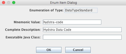
Hydstra ‘Self Identifying’ Format
As of OpenDCS 6.3 RC08, support is provided for a variation on the Hydstra format which the Kisters’ documentation refers to as ‘Self Identifying’. If you add a property ‘selfIdent’ set to TRUE, then additional columns will be added. The following table shows the columns in the normal Hydstra format (described above) and the Self Identifying format:
Hydstra Normal |
Hydstra Self Identifying |
|---|---|
#V2 (literal) |
|
Site (padded) |
Site (unpadded) |
DataSrc (empty) |
|
Data Type Code FFFF.FF |
Data Type Code (no padding) |
DateTime YYYYMMDDHHMMSS |
DateTime YYYYMMDDHMMSS |
Data Value |
Data Value |
qualcode |
qualcode |
datatrans |
datatrans |
maxgap |
maxgap |
“DECUM” or empty. Indicates value need decumulation |
An example of self-identifying format is as follows:
Additional columns are:
The first column is always the literal #V2.
The Optional Data Source field is always empty
The last column will be the word “DECUM” or nothing. If you add a sensor property HydstraDecum=true, then DECUM will be printed.
USBR Hydromet DMS3 Formatter
Add the following entry to the enumeration for Output Formatters (using the ‘rledit’ program):
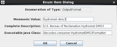
Mnemonic: hydromet-dms3
Full Name: U.S. Bureau of Reclamation Hydromet DMS3
Java Class Name: decodes.consumer.HydrometDMS3Formatter
yyyyMMMdd hhmm cbtt PC NewValue OldValue Flag user:regtest # DECODES output
# Platform GALW2, Timezone=EST
2014FEB24 1000 GALW2 HP 17.21 998877.00 -20
2014FEB24 0900 GALW2 HP 17.37 998877.00 -20
2014FEB24 1000 GALW2 HT 38.71 998877.00 -20
2014FEB24 0900 GALW2 HT 38.86 998877.00 -20
2014FEB24 1000 GALW2 PC 4.39 998877.00 -01
2014FEB24 0900 GALW2 PC 4.39 998877.00 -01
At the very beginning of a routing spec run, a single header line is printed as shown in blue. The name of the currently logged-in user is included (“regtest”) in the example.
Whenever a new platform is being decoded a platform header line is printed as shown in green. The site name is included along with the time zone assigned to the site.
Note: For this formatter, time zones should always be assigned to your site records.
Each sample value is then printed in the exact format shown:
Date/Time in “yyyyMMMdd HHmm” format in the time zone assigned to this site.
The site name – up to 8 characters, left justified in the field. The CBTT name is selected if one is present. If not, the preferred site name (as specified in your DECODES settings) is shown.
The data type code – up to 8 characters, left justified in the field. If a CBTT data type standard is defined, it is used. Otherwise, the preferred data type code (as specified in your DECODES settings) is shown.
The data value is shown left justified in a 10-character field. Two fractional digits are always included.
The “Old Value” coming from DECODES is always 998877.00. DECODES does not have historical context to print old values.
A 4-character flag field is shown (see possible values below.
Sensor max/min limits are used by this formatter. The limits can be assigned in the DECODES Configuration record (to apply to all platforms sharing the configuration). They may be overridden by max/min values in the Platform Sensor record.
Values outside the max/min range are still shown in the output, but with special flag values:
Flag Value |
Meaning |
|---|---|
-01 |
Good Data |
-02 |
No value. This can occur if the raw data indicated missing data or if the field was garbled and could not be decoded. In this case the value will also be 998877.00 |
-20 |
Low limit exceeded |
-22 |
High limit exceeded |
Kisters ZRXP Formatter
The Kisters WISKI database supports an input format called ZRXP. This formatter outputs data as required by ZRXP.
If you originally installed an OpenDCS release prior to 6.1, you will have to add the Enumeration record manually in order to use the Kisters ZRXP formatter. Start the Reference List Editor with the “rledit” command. Then select the OutputFormat enumeration. Click Add and fill out the form as shown in Figure 20.
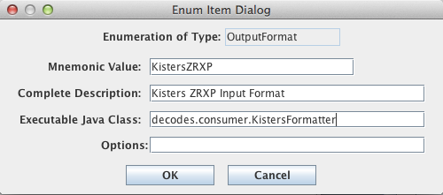
Figure : Enumeration for Kisters ZRXP Formatter.
The formatter takes properties as shown in Table 3.
Prop Name |
Ty pe |
Default |
Description |
|---|---|---|---|
SitePrefix |
St ring |
(empty) |
Enter a string that will precede the SITENAME on the header line. For AESRD this will be “collect.”. |
SiteNameType |
Enum |
NWSHB5 |
Primary site name type. |
Si teNameTypeAlt |
Enum |
Local |
Alternate Site name type |
Dat aTypeStandard |
Enum |
SHEF-PE |
Primary Data Type to use in the header. |
DataTy peStandardAlt |
Enum |
SHEF-PE |
Alternate data type to use in the header |
includeTZ |
Boo lean |
true |
Set to true to include the parameter TZ followed by the time zone name in the header. |
tzName |
St ring |
(empty) |
The routing spec is assigned a time zone when it runs. Normally you can leave this empty and it will be filled in by whatever timezone the routing spec is using. Setting a value here will override the name used by the routing spec but it will not actually change the computed time zone of the time stamps. So use this property with extreme caution. |
includeCNAME |
Boo lean |
false |
Set to true to include a sensor name in the header preceded by CNAME. For AESRD we will leave this as false. |
includeCUNIT |
Boo lean |
false |
Set to true to include the engineering units in the header. For AESRD we will leave this as false. |
includeRINVAL |
Boo lean |
true |
If true then the “Invalid Value” specifier RINVAL will be included in the header. If false, then invalid values will be omitted from the data output. |
RINVAL |
St ring |
-777 |
The default invalid value specifier. Set to the string “omit” to have invalid values simply omitted from the output. |
includeLayout |
Boo lean |
false |
If true, then include a separate header line with the ZRXP layout spec. This is required for ZRXP 3.0. |
An example of Kixters ZRXP formatter is:
#REXCHANGEcollect.BUHW.PR|*|TZMST|*|
20200828061500 514.50
20200828063000 514.50
20200828064500 514.50
20200828070000 514.50
#REXCHANGEcollect.BUHW.AT|*|TZMST|*|
20200828070000 7.5
#REXCHANGEcollect.BUHW.VB|*|TZMST|*|
20200828070000 12.9000
Each sensor has a header line that begins with the string #REXCHANGE. The code then builds an Exchange ID from information in the DECODES database. The first Exchange ID shown above is “collect.BUHW.PR”. This is built as follows:
The sitePrefix property was set to “collect.”
The siteNameType property was set to local. The local name for this station is “BUHW”.
DataTypeStandard was set to SHEF-PE and the client has (incorrectly) entered “PR” as the data type as an abbreviation for Precip.
Other parameters may appear on the header such as the RINVAL number, which is used to replace invalid data values. The Time Zone is included above. The Units may be included, etc.
CSV Formatter
The CSV formatter can print your message data in comma/tab delimited format.
If you originally installed an OpenDCS release prior to 6.2, you will have to add the Enumeration record manually in order to use this formatter. Start the Reference List Editor with the “rledit” command. Then select the OutputFormat enumeration. Click Add and fill out the form as shown in Figure 21
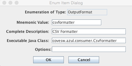
Figure : Enumeration for CSV Formatter.
The formatter takes properties as shown below:
Prop Name |
Ty pe |
Default |
Description |
|---|---|---|---|
delimiter |
St ring |
, (i.e. a single comma) |
Change to \t for tab delimited, or enter any other string for a custom delimiter. |
dataTypes |
St ring |
(empty) |
a comma-separated list of data type codes. Use this if you always want a particular set of columns in a particular order If not specified (the default), then all sensors in a given message are printed in sensor order. |
timeFormat |
St ring |
MM/ dd/yyyy,HH:mm:ss |
The format for the date/time column(s). See Java API docs for ja va.text.SimpleDateFormat. |
missingValue |
St ring |
(empty) |
Set this if you require a special string to denote missing data. |
noHeader |
Boo lean |
false |
Set to true if you do not want any header lines. Usually used in conjunction with dataTypes so that the order of columns is fixed and known. |
header EveryMessage |
Boo lean |
true |
Default is to print a new header line at the start of every message. Set to false to only print the header once. |
XML-1 Formatter
The XML-1 Formatter prints your message data in an XML format. This format is suitable for subsequent import into commercial time series database products such as Aquatic Informatics’ Aquarius.
If you originally installed an OpenDCS release prior to 6.3 RC07, you will have to add the Enumeration record manually in order to use this formatter. Start the Reference List Editor with the “rledit” command. Then select the OutputFormat enumeration. Click Add and fill out the form as shown in Figure 22.
Be sure to enter the Executable Java Class exactly as shown:
covesw.azul.consumer.DecodesXml1Formatter
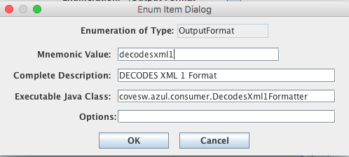
Figure : Enumeration for XML-1 Formatter
The formatter takes the following properties:
Prop Name |
Type |
Default |
Description |
|---|---|---|---|
dateFormat |
String |
yyyy/MM/dd-HH:mm:ss |
Java SimpleDateFormat specifier for all date/times in the output. Note that times will be printed in the timezone assigned in the DECODES routing spec. |
includeSiteAliases |
boolean |
false |
Normally only the preferred site name is printed. Set this to true to have SiteAlias records included with all names defined in the DECODES database. |
The following is an example of the output format. It shows four sensors located at the main platform’s site and two at an alternate site (That is, the Actual Site in the platform record is set to some other site).
<DcpData Dcpaddr="CAB00592" Quality="G">
    <TimeZone>MST</TimeZone>
    <SystemTime>2017/03/02-15:23:09</SystemTime>
    <MessageTime>2017/03/02-15:10:01</MessageTime>
    <FailureCode>G</FailureCode>
    <SignalStrength>43</SignalStrength>
    <FrequencyOffset>0</FrequencyOffset>
    <ModulationIndex>N</ModulationIndex>
    <Site local="SomeSiteName">
        <Sensor shefcode="TA" name="AirTemp" units="degC">
            <Value time="2017/03/02-15:00:00">-5.5000</Value>
        </Sensor>
        <Sensor shefcode="US" name="WindSpeed" units="M/s">
            <Value time="2017/03/02-15:00:00">20.7000</Value>
        </Sensor>
        <Sensor shefcode="UD" name="WindDir" units="deg">
            <Value time="2017/03/02-15:00:00">133.0000</Value>
        </Sensor>
        <Sensor shefcode="HG" name="WaterLevel" units="m">
            <Value time="2017/03/02-15:00:00">0.315</Value>
        </Sensor>
        <Sensor shefcode="VB" name="Battery" units="V">
            <Value time="2017/03/02-15:00:00">14.120</Value>
        </Sensor>
    </Site>
    <Site local="AltSite">
        <Sensor shefcode="HG" name="AltWaterLevel" units="m">
            <Value time="2017/03/02-15:00:00">5.011</Value>
        </Sensor>
        <Sensor shefcode="VB" name="AltBattery" units="V">
            <Value time="2017/03/02-15:00:00">12.700</Value>
        </Sensor>
    </Site>
</DcpData>
Figure : XML-1 Format Example
HydroJSON Formatter
The HydroJSON formatter formats message data in HydroJSON format. For information on this format see:
https://github.com/gunnarleffler/hydroJSON
If you originally installed an OpenDCS release prior to 6.3, you will have to add the Enumeration record manually in order to use this formatter. Start the Reference List Editor with the “rledit” command. Then select the OutputFormat enumeration. Click Add and fill out the form as shown in the figure below.
Note: It is important that the Executable Class be exactly as shown.
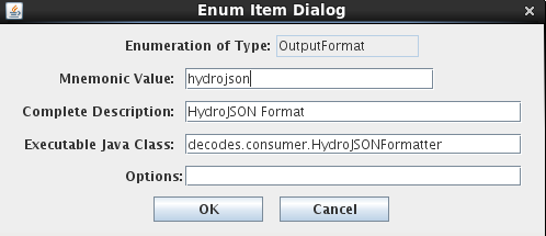
Figure : Enumeration for HydroJSON Formatter.
The formatter takes properties as shown below:
Prop Name |
Ty pe |
Default |
Description |
|---|---|---|---|
timeFormat |
St ring |
%Y- %m-%dT%H:%M:%S%z |
Format for the C strftime method. |
siteNam eTypePreference |
St ring |
CWMS |
If you want to use a site name other than CWMS, set this property. |
TsImport Formatter
OpenDCS has a utility called “importts” which can take files in a certain format and ingest them into the time series database. This works for HDB, CWMS and OpenTSDB. The “TsImport” formatter will output DCP data in this format.
If you installed prior to version 6.7 you probably do not have this format in your database. To add it, start the Reference List Editor with the “rledit” command. Then select the OutputFormat enumeration. Click Add and fill out the form as shown in the figure below.
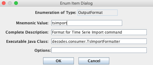
Figure : “tsimport” formatter in rledit
The format requires that enough information be in the sensor records to build a complete time series identifier (TSID). In HDB, a TSID has 4 or 5 parts:
Site.DataType.Interval._R (For Real Data)
Site.DataType.Interval._M.ModelId (For Modeled Data)
For CWMS and OpenTSDB, a TSID has six parts:
Location.Param.ParamType.Interval.Duration.Version
See the sections on the HDB Consumer or CWMS Consumer for detailed instructions on how DECODES maps sensor information into a multi-part TSID. (Note: The information in the CWMS consumer is applicable to OpenTSDB.)
SNOTEL Formatter
The SNOTEL formatter was prepared for the ASRC Federal SNOTEL project for USDA. This formatter is available in OpenDCS 6.8 RC02 and later versions.
To use the formatter, start the Reference List Editor (rledit command). On the Enumerations tab, select the Output Format enumeration. Then add an entry as shown below:
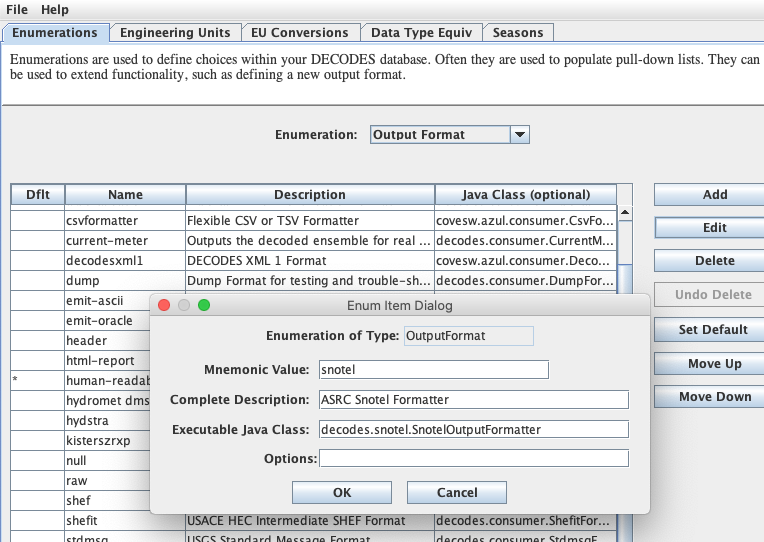
Make sure the Executable Java Class is exactly as shown:
decodes.snotel.SnotelOutputFormatter
The SNOTEL Output Formatter is somewhat different than other formatters in that it takes a raw message and does its own decoding without using any of the DECODES platform, site, or config records.
You must provide a specification file in the following format:
Next, Open the DECODES Settings dialog and set the variable named ‘snotelSpecFile’ to the name of the file.
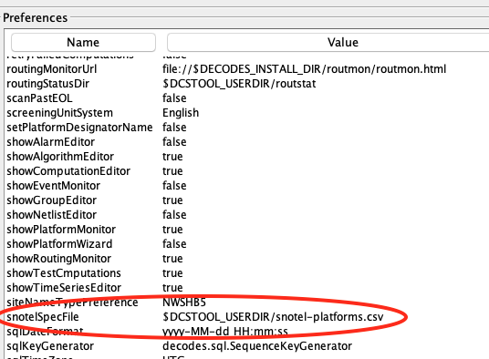
Next, you create a routing spec as you normally would. There is no need to specify platform selection by IDs or network lists. The code will build a list of platforms to process from the spec file that you provide.
Note that the snotelSpecFile may be specified in the routing spec properties in addition to the DECODES Settings, as shown above. The setting in the routing spec will override the setting in DECODES Settings. Thus you could have multiple routing specs, each using a differen spec file if desired.
The routing spec shown below uses a Directory Destination. Note the filenameTemplate property setting. Thus files will be created in the directory ‘snotel-out’ under the DCSTOOL installation. Files will be named as shown with a time stamp and a sequence number. Example: snotel-20200917-153102-3
The ‘useSysDate’ property tells the code to use the system time for building the file name, rather than the message time. The $SEQUENCE in the file name guarantees that each name will be unique.
The optional bufferTimeSec property is set to a positive number of seconds. This enables a buffering feature. Without this, a separate file will be created for each message. Setting it to 5, as shown, means that data will be buffered and a new file created every five seconds. Thus if you are processing a large amount of historical data, this will prevent a flood of very small files.
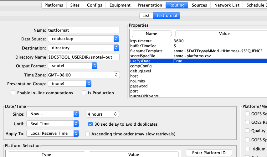
DECODES Consumers
Consumers receive the formatted data created by DECODES and send it somewhere. The list of consumers available to you is controlled by the reference list editor. Type “rledit” at the command line. Select the Enumerations Tab, and Data Consumer.
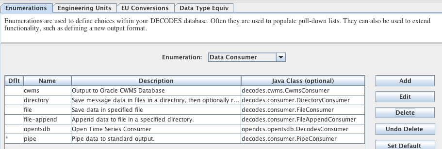
Figure : Reference List Editor - Consumer Enumeration.
Pipe Consumer
The Consumer Argument should be one of:
‘stdout’ – send data to standard output.
‘stderr’ – send data to standard error.
command - an arbitrary command line. The command will be executed and the data will be piped to the command’s standard input.
PipeConsumer will use the following routing-spec properties to control its actions:
Property Name |
Default |
Description |
ConsumerBefore |
none |
An encoded string that is written to the file preceding each message. The string may contain UNIX-style escape sequences such as \n \r \t, and octal binary characters encoded as \002, etc. |
ConsumerAfter |
none |
An encoded string that is written to the file after each message. |
File Consumer
The Consumer Argument should be the file name template. The file will be opened when the routing spec starts. All data from the routing spec will be placed in the file. The file will be closed when finished.
The file name template may contain a variable of the form $DATE(format) where format describes how the date/time stamp is to be formatted in the file name. It can contain any format handled by the Java class java.text.SimpleDateFormat, although since it is used as a filename, it should not contain spaces or other illegal characters.
See http://java.sun.com/j2se/1.4.1/docs/api/ for complete docs on SimpleDateFormat. Click on “java.text” in the upper left frame. Then click on SimpleDateFormat in the lower left frame.
For example, if Consumer Arg is “data-$DATE(yyyyMMdd-HHmmss)”, this might result in a filename data-20031213-120000.
This consumer should therefore only be used with routing specs that run for a finite period of time. That is, the ‘until’ time should be specified if reading from an LRGS.
FileConsumer will use the following routing-spec properties to control its actions:
Property Name |
Default |
Description |
ConsumerBefore |
none |
An encoded string that is written to the file preceding each message. The string may contain UNIX-style escape sequences such as \n \r \t, and octal binary characters encoded as \002, etc. |
ConsumerAfter |
none |
An encoded string that is written to the file after each message. |
file.overwrite |
false |
Set this property to true if you want the consumer to overwrite files that already exist. The default behavior is to append to the existing file. |
cmdAfterFile |
none |
A command that DECODES will execute after each file is generated and placed in the directory. The command may contain $FILENAME which will be replaced with the name of the file just completed. |
cmdTimeout |
In teger |
Number of seconds for cmdAfterFile to complete. Default=60 seconds. |
Directory Consumer
The Consumer Argument should be a directory name. The routing spec will create a separate file in this directory to hold the data generated for each message. The file name will be in the following format:
SiteName-YYYYMMDDHHmmSS
Hence when looking at a sorted directory listing you will see each platform’s files together in time order.
The Site Name used will be the default site name type defined in your DECODES properties file.
DirectoryConsumer will use the following routing-spec properties to control its actions:
Property Name |
Def ault |
Description |
ConsumerBefore |
none |
An encoded string that is written to the file preceding each message. The string may contain UNIX-style escape sequences such as \n \r \t, and octal binary characters encoded as \002, etc. |
ConsumerAfter |
none |
An encoded string that is written to the file after each message. |
cmdAfterFile |
none |
A command that DECODES will execute after each file is generated and placed in the directory. The command may contain $FILENAME which will be replaced with the name of the file just completed. |
cmdTimeout |
I nteger |
Number of seconds for cmdAfterFile to complete. Default=60 seconds. |
filename |
none |
A file-name template to override the default described above. (see below) |
Files will be constructed in a temporary location and then moved to the named directory. Therefore, you can write a program to scan the directory for new files and be assured that all files in the directory are complete.
If you supply a filename property, it will be used to construct the filename, overriding the default described above. The template may contain variables of the following form:
$DATE(format) - See the description of this in section 8.2 .
$TRANSPORTID - will be replaced by the DCP address.
$SITENAME - will be replaced by the site name.
$SEQUENCE – Use this to ensure uniqueness. This will be replaced by an increasing integer starting with 1 for the first file output from the consumer.
CWMS Consumer
The USACE (U.S. Army Corps of Engineers) CWMS (Corps Water Management System) stores uses a time-series database to store water-level and related data. The DECODES software suite has a module allowing it to place incoming data directly into the CWMS database. This obviates the need for intermediate flat-files used in the pass.
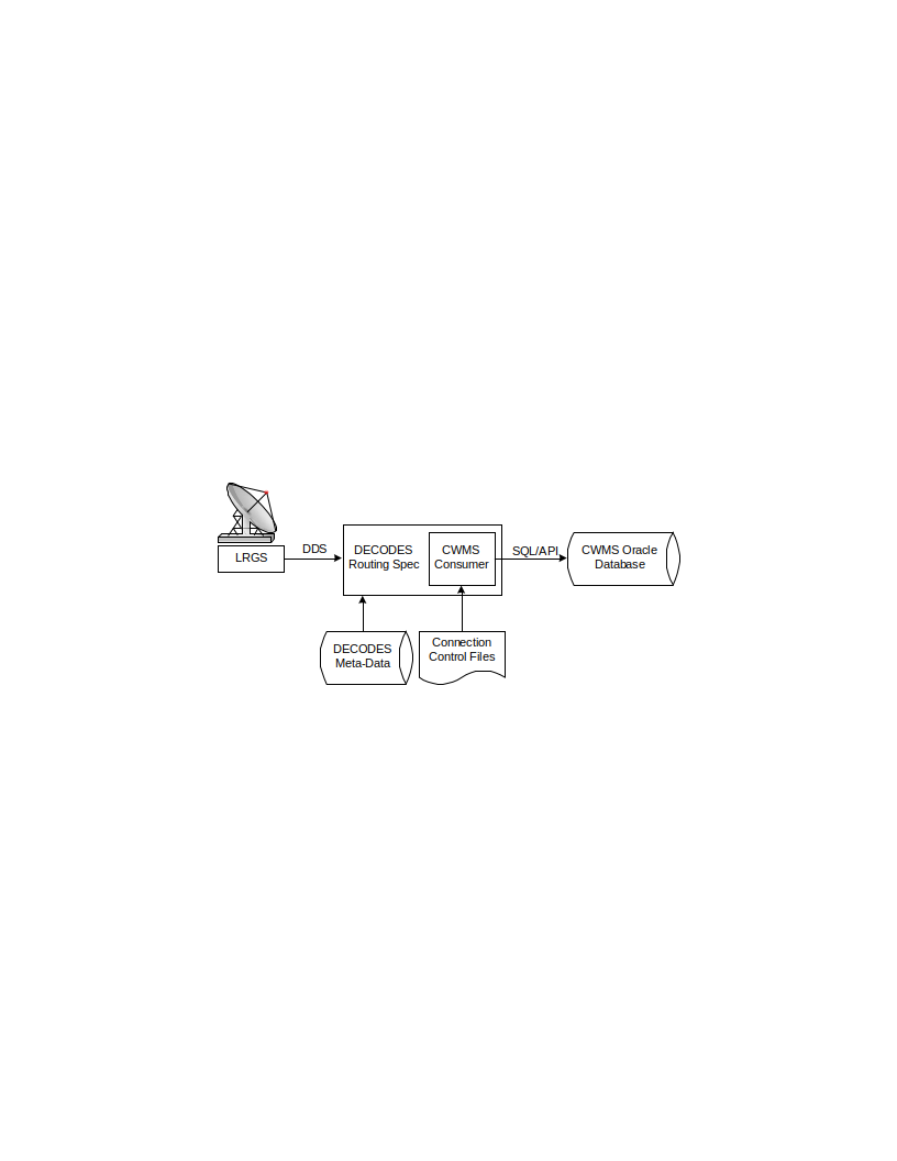
Figure ‑: CWMS Consumer Data Flow
The “CWMS Consumer” is selected as the output (consumer) module in the routing spec. It receives the decoded data from the routing spec and stores it in the CWMS Oracle Database. The CWMS Consumer uses the AQL API (Application Program Interface) published by HEC to write time-series data directly to CWMS.
We have tried to make the CWMS Consumer as automatic as possible. It has hard-coded defaults for time-series storage parameters that can be used in most cases. For special cases, the consumer allows you to provide properties in the DECODES database to override the defaults.
Control files tell DECODES how to connect and authenticate to the CWMS database.
This section will explain how to set up DECODES to store data directly into a CWMS database.
Set up DECODES for CWMS
CWMS requires some additions to the DECODES Database:
New “CWMS” Site Name Type
New “CWMS” Parameter Data Type
Several Engineering Units (CWMS is very particular about what EUs it will accept).
Unit Converters to convert from other DECODES units to the ones that CWMS recognizes.
A new “CWMS” Data Consumer Type
A “Null” Output Formatter
We have prepared an XML file containing these items. To import these items into your DECODES database, open a terminal window. Then CD to the DECODES_INSTALL_DIR directory. Then:
bin/dbimport –r to_import/cwms-import.xml
(If you are working on a Windows machine, substitute backslash for slash in the above).
CWMS Connection Parameters
Two files are required: A Properties file stores the CWMS connection and default parameters. An encrypted file stores the username and password to use when connecting to CWMS.
The CWMS Properties File
Create a text file in the $DECODES_INSTALL_DIR called “decodes-cwms.conf”. This is a text file containing ‘name=value’ pairs, one per line. The following table explains the parameters, whether or not they are required, and what the default value is. The parameter name is not case sensitive.
Name |
Default Value |
Description |
TimeZone |
GMT |
Optional time zone in which CWMS Database will represent date/time stamps. |
dbUri |
No default value provided |
Required parameter in the form: host:portnumber:SID This tells DECODES the location of the CWMS database. Example: 155.76.210.137:1521:MVRT) |
jdbcOracleDriver |
Optional Oracle JDBC Driver String. The default driver is “thin” but you can change it to “oci”. If “oci” is used native code will have to be installed. No need to modify this property. |
|
cwmsVersion |
Raw |
Optional: This is used as the default “Version” part of the time-series descriptor. |
cwmsOfficeId |
No default value provided |
Required: This is the CWMS office ID passed to the API “store_ts” procedure. Typically this is your 3-character district abbreviation. Example: MVR |
DbAuthFile |
$DECODES_INSTALL_DIR/ .cwmsdb.auth |
Optional: Set this if you want to stored the database authentication file in a different location. |
shefCwmsParamFile |
$DECODES_INSTALL_DIR/ shefCwmsParam.prop |
Optional: Set this if you want to store the SHEF to CWMS mapping in a different file. |
Encrypted Username/Password File
The CWMS Consumer will look for a file called “.cwmsdb.auth” in the directory $DECODES_INSTALL_DIR. This file will contain the needed login information in an encrypted form.
A script called “setCwmsUser” has been prepared to facilitate creating or modifying the file. This script must be run in a terminal session:
cd $DECODES_INSTALL_DIR
bin/setCwmsUser
(enter username & password when prompted).
chmod 600 .cwmsdb.auth
If this is a Windows system, open a DOS (“cmd”) window and type:
cd %DECODES_INSTALL_DIR%
binsetCwmsUser
The program will ask you for a username and password. These will be encrypted and stored in the file.
After creating the file for the first time, you should set its permissions so that only you have access to it:
chmod 600 .cwmsdb.auth
Note: The file should be owned by the user who will run the DECODES routing spec. The routing-spec will need permission to read this file.
Optional CWMS Parameter Mapping File
DECODES must build a time-series descriptor that contains a valid CWMS “Parameter Type”. Since most of the Corps is currently using DECODES with SHEF codes, we have provided a way to automatically map SHEF codes to CMWS Parameter Types.
Note: See section 8.4.4 for a more complete description on how DECODES builds the descriptor. You can specify CWMS data-types directly in the DECODES database, bypassing SHEF altogether.
DECODES can do the mappings listed in Table 6‑7 automatically. If these are sufficient for you, then you do not need to create a mapping file.
SHEF Code |
CWMS Param Type |
PC |
Precip |
HG |
Stage |
HP |
Stage-Pool |
HT |
Stage-Tail |
VB |
Volt |
BV |
Volt |
HR |
Elev |
LF |
Stor |
QI |
Flow-In |
QR |
Flow |
TA |
Temp-Air |
TW |
Temp-Water |
US |
Speed-Wind |
UP |
Speed-Wind |
UD |
Dir-Wind |
If the above defaults are not adequate, you may provide a mapping file to override or supplement them. Prepare a text file “shefCwmsParam.prop” and place it in $DECODES_INSTALL_DIR. This is a Java properties file, containing name=value pairs, one per line. For example, to have SHEF “HP” map to CWMS Param Type “Stage”, add a line as follows:
HP=Stage
The CWMS Time Series Descriptor
A CWMS Time-Series descriptor has six parts. Each part is separated with a period:
Location . Param . ParamType . Interval . Duration . Version
We have designed the DECODES CWMS Consumer for convenience and flexibility: For convenience, DECODES can build the descriptor automatically, using information that it already has in the DECODES database. For flexibility, you can explicitly set part or all of the descriptor in special circumstances.
The following subsections describe each part of the descriptor.
Location
The Location corresponds to a DECODES site name. DECODES allows each site to have multiple names of different types. It also allows each site to specify which name-type to use by default (see the “SiteNameTypePreference” parameter in your “decodes.properties” file).
So, if you have CWMS set up with the same names that you use in DECODES, then you do not need to do anything else.
The consumer will build the location as follows:
If a site-name with type “CWMS” exists, use it.
Otherwise, use the default site name.
See below for instructions on creating an explicit CWMS site-name-type.
Param
The ‘Param’ part must exactly-match one of the CWMS parameter in your database. The preferred way is to specify an explicit “CWMS” data-type in the Config Sensor record, as shown below.
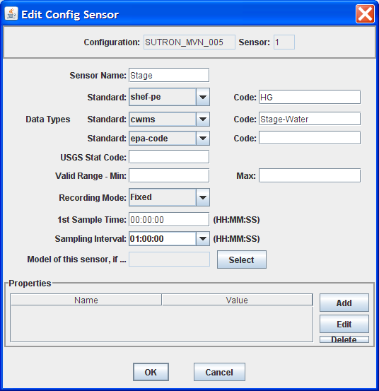
Figure : Config Sensor with Explicit CWMS Data Type
If no explicit CWMS data-type is specified, then the Consumer will attempt to map it from a SHEF code. The consumer will use the mapping specified in the file described in section 8.4.3, or a default mapping listed in Table 6‑7 if the SHEF code is not found in the file.
ParamType
By default the consumer will set ParamType to “Inst”. You can override this by adding a sensor property to the DECODES database called “CwmsParamType”.
Set a Config Sensor Property if you want the value to be applied to all platforms using shared configuration. Use a Platform Sensor Property to apply the value to a single platform.
Other valid settings for ParamType include: “Ave”, “Max”, “Min”, or “Total”.
Interval
The Interval part specifies the period at which this parameter is measured. DECODES already has this information in each sensor record. It can build the appropriately-formatted string.
If for some reason you need to override the setting the DECODES automatically selects, you can add a sensor property called “cwmsInterval” followed by the string you want to use.
Duration
The Duration part should be “0” for data with a ParamType of “Inst”. DECODES will handle this automatically. For other types (specified by a sensor property), DECODES will build a duration string matching the sensor period. The user can override this choice by adding a sensor property called “CwmsDuration”.
Version
The Version is used by different districts in different ways:
Some districts always use a constant value like “Raw” for data ingested from DECODES.
Other districts use the Version component to denote the source of the data. That is, which LRGS, DRGS, or file provided the data.
Some districts need to use a different Version component for each parameter.
The CWMS Consumer accommodates all three situations:
To always use a constant value, set the “cwmsVersion” parameter in the CWMS Properties file as described above in section 0.
To have the Version denote the Source of the data: set up separate DECODES routing specs for each source. Add a routing spec property called “cwmsVersion” set to the appropriate value. A routing spec property, if supplied, will override the value in the CWMS Properties file.
To have a particular version for a particular parameter, add a sensor property called “CwmsVersion” containing the desired value. A sensor-setting will override any other values.
The CMWS Office ID
Under CWMS 3.0 the office ID is automatically determined when the user logs in. If the user has privileges in more than one office then set the following property in the DECODES Settings menu (or edit the decode.properties file directly):
CwmsOfficeId=MVK
Set this to the appropriate code for your USACE Office.
You can also specify this as a routing-spec property called “CwmsOfficeId”. This gives you flexibility: The properties file can contain the default. Individual routing specs may override the default if they process data from another office.
For CWMS 2.1, the decodes.properties setting is used exclusively, so it is always recommended that you set it correctly.
The “Store Rule”
The store rule value is used to control how to handle the insertion of data samples that already exist in the CWMD database.
By default, the consumer will set the store rule to “Replace All”. You may override this by adding a routing-spec property with the desired setting. The valid values are:
Replace All
Delete Insert
Replace With Non Missing
Replace Missing Values Only
Do Not Replace
Refer to the API User’s Manual for more information on the store rule field.
Override Protection
This value determines how CWMS will override existing data in the database. By default, the consumer sets this to 1 (true). To set it to false (0), add a routing-spec property called “OverrideProt” set to a value of “0”.
Refer to the API User’s Manual for more information on the override protection field.
Version Date
NOT USED ON CURRENT CWMS DATABASE. Default value is null. Refer to the CWMS Oracle API User’s Manual for more information on this field
Create the Routing Spec
Open the DECODES database editor and create a new routing spec in the normal manner. For Consumer Type, select “cwms”. For Output Format, select “null”.
As stated above, the properties shown below may be used to override the built-in defaults. Property names are not case-sensitive.
Name |
Description |
CwmsOfficeId |
Overrides setting in decodes-cwms.conf file. |
StoreRule |
Overrides built-in default of “Replace All” |
OverrideProt |
Overrides built-in default of 0 (false). Set to 1 for true. |
VersionDate |
NOT USED ON CURRENT CWMS DATABASE VERSION. Default value null. Refer to the CWMS Oracle API User’s Manual for more information. |
We also recommend that you select the “CWMS” presentation group. This will ensure that your data is converted into EUs that CWMS will accept.
Engineering Units
The sensor engineering-units need to be in compliance with the CWMS Oracle Database, otherwise the sensor data will not be accepted by CWMS. We have prepared a presentation group that will automatically convert your data into CWMS EUs. You simply have to select the presentation group in the routing spec.
The figure below shows the database editor with the CWMS-Metric presentation group open. See how the presentation group asserts which units should be used for each parameter type. When you apply the presentation group to a routing spec, DECODES will automatically convert the data into the correct units.
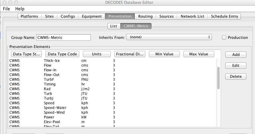
Figure : CWMS-Metric Presentation Group.
Refer to the section on Presentation Groups in the DECODES User Guide. Recall that you can also use the presentation group to omit certain parameter types from the output. For example, if you do not store battery voltage in the CWMS database, change the units for VB to ‘omit’.
Troubleshooting
The DECODES Routing Spec sends log messages to a file in the “routstat” directory under $DECODES_INSTALL_DIR. Find the file there with the same name as your routing spec and an extension “.log”. For example if your Routing Spec is called “cwms_rs”, the log file name will be: cwms_rs.log.
The remainder of this section will provide examples of possible log messages, explaining what each means and what to do to correct the situation. A ‘FATAL’ message will result in the termination of the routing spec.
FATAL 03/06/07 16:56:46 CwmsConsumer Cannot load configuration from
‘$DECODES_INSTALL_DIR/decodes-cwms.conf': java.io.IOException:
CwmsDbConfig Cannot open config file 'C:\DCSTOOL/decodes-cwms.conf':
java.io.FileNotFoundException: C:\DCSTOOL\decodes-cwms.conf (The
system cannot find the file specified)]
This fatal message means that the decodes-cwms.conf file was not found under the required directory. Make sure that the decodes-cwms.conf file is located under the DECODES installed directory.
WARNING 03/06/07 16:31:26 CwmsConsumer Cannot read DB auth from file
'C:\DCSTOOL/.cwmsdb.auth': java.io.FileNotFoundException:
C:\DCSTOOL\.cwmsdb.auth (The system cannot find the file specified)
This warning message means that the authentication file, which contains the encryption of the username and password for the Database connection, is not on the right directory. Make sure that the .cwmsdb.auth file is located under the DECODES installed directory.
FATAL 03/06/07 16:31:26 CwmsConsumer Error getting JDBC ORACLE
connection using driver 'jdbc:oracle:thin:@' to database at
'155.76.210.137:1521:MVRT' for user '': java.sql.SQLException:
invalid arguments in call
CWMS Data Consumer will log Database connection fatal messages if:
The wrong username/password was sent to it, which in this case make sure that the authentication file (.cwmsdb.auth) is on the right directory and contains the right username and password (this is the sample log shown above)
The wrong CWMS Database connection information was supplied; in this case make sure that the DbUri property on the decodes-cwms.conf file contains the right Database connection information
The CWMS Database server is down, in this case call the CWMS Database system administrator
WARNING 03/06/07 17:03:17 CwmsConsumer Cannot read properties file
'C:\DCSTOOL/shefCwmsParam.prop': java.io.FileNotFoundException:
C:\DCSTOOL\shefCwmsParam.prop (The system cannot find the file
specified)
This warning message means that the shefCwmsParam.prop file was not found under the DECODES installed directory. However, this file is not required. If the user has decided not to use this file no action need to be taken. If not, make sure that this file exists under the DECODES installed directory.
WARNING 03/06/07 15:30:59 CwmsConsumer Platform Site Name
nwshb5-STBI4, Platform Agency MVR, DCP Address CE2DC544, sensor HG
Error while inserting sensor data in cwms_ts.store_ts CWMS procedure
:java.sql.SQLException: ORA-20010: INVALID_OFFICE_ID: "tttMVR" is not
a valid CWMS office id
This warning message means that the office that was set on the decodes-cwms.conf file is not valid for the CWMS Database. Make sure that the decodes-cwms.conf file contains the correct office value on the cwmsofficeid property.
WARNING 03/05/07 16:22:40 CwmsConsumer Platform Site Name
nwshb5-STBI4, Platform Agency MVR, DCP Address CE2DC544, sensor VB
Error while inserting sensor data in cwms_ts.store_ts CWMS procedure
:java.sql.SQLException: ORA-20210: WARNING(cwms_loc.get_ts_code):
STBI4.Volt.Inst.1Hour.0.raw FOR OFFICE: MVR NOT FOUND
This warning message means that the time-series descriptor does not exists in the CWMS Database. Make sure that the CWMS Database contains the time-series descriptors specified in the warning message. In this case ‘STBI4.Volt.Inst.1Hour.0.raw’ for office MVR.
FAILURE 02/23/07 15:20:13 RoutingSpec(CWMSTEST) Error on data
consumer 'cwms': decodes.consumer.DataConsumerException: CwmsConsumer
Error while inserting sensor data in cwms_ts.store_ts CWMS procedure
:java.sql.SQLException: ORA-20103: Requested unit conversion is not
available
This warning message means that the CWMS Database does not recognize the unit value that CWMS Data Consumer sent. Make sure that the sensor unit is accepted by the CWMS Database, you may need to create a DECODES presentation group to convert units if the CWMS Database does not handle the current senor unit. Refer to the DECODES Presentation group on the DECODES User Manual for more information.
WARNING 03/05/07 16:34:36 CwmsConsumer Platform Site Name
nwshb5-CRVI4, Platform Agency MVR, DCP Address CE637FAC, sensor YA
Cannot find CWMS or SHEF datatype -- skipping.
This warning message means that the time-series descriptor was not created for that particular sensor. Change the sensor data type to cwms with the correct cwms code (this is done on the Edit Config Sensor dialog) or add the mapping of that sensor data type code on the shefCwmsParam.prop file.
TCP Client Consumer
TCP Client Consumer is included in OpenDCS Versions 6.4 RC08 and later.
The TCP Client Consumer will connect to a remote server and send the data in the format you have specified.
Previous versions contained a “socketclient” enumeration with an incorrect Java Class name.
Start the Reference List Editor from the Windows Start menu or with the “rledit” command. On the Enumerations tab, select the Data Consumer enumeration. Select the “socketclient” entry and click edit. Or, if none exists, click Add. Fill out the form as shown below. It is important that the executable Java Class be exactly as follows:
decodes.consumer.TcpClientConsumer
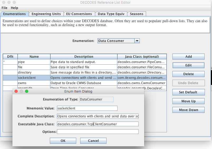
Before exiting the reference list editor, click File – Save to DB.
Now restart your OpenDCS GUI if it was already running to re-initialize its reference lists. Go to the DECODES Database Editor – Routing tab. Open the Routing Spec you want to use.
Under Destination, select “socketclient”. This will match the enumeration entry you added above. Note that the label for the text field just below this now changes to “Host:Port”. Type in the hostname (or IP Address) and port number that the server is listening on, separated by a colon.
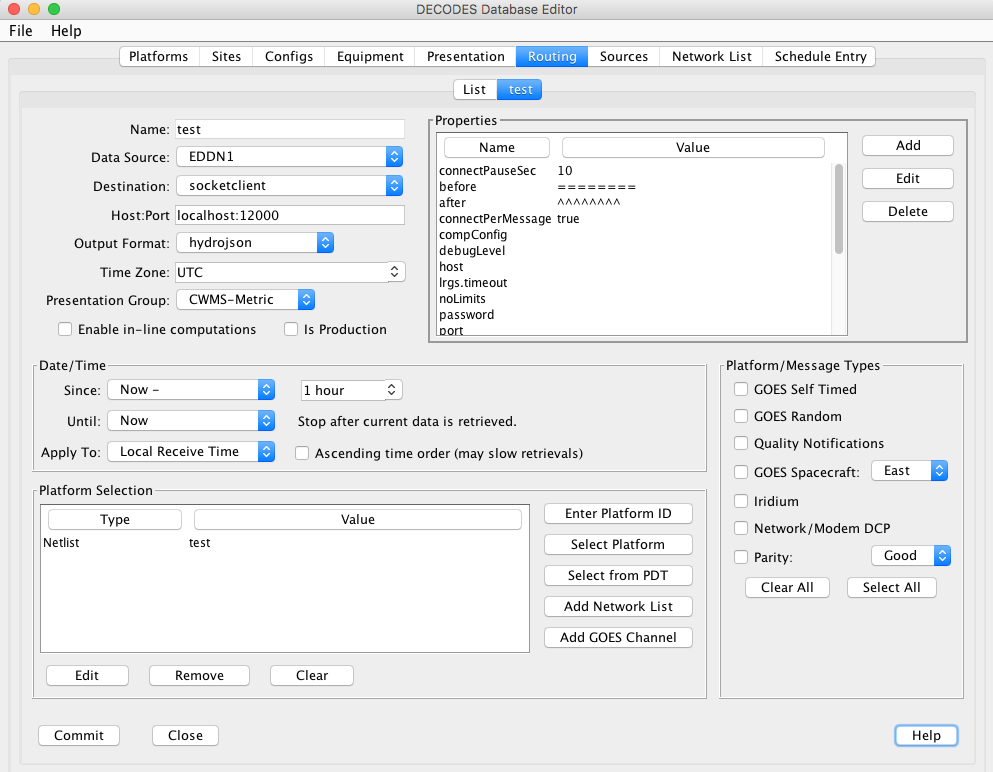
The TCP Client Consumer has options that are activated by properties:
connectPerMessage – (default=false). Add this property with a value of true to have the client establish a separate connection for each message. The default is to leave the connection open and reuse it.
before – An optional string sent before the start of each message
after – An optional string sent after the end of each message
connectTries – (default=3) Connections may fail for a variety of reasons such as network issues, server reboot, etc. The client will try to connect this many times before declaring that the routing spec has failed.
connectPauseSec – (default=60) The client will pause this many seconds between connection attempts.
Running the Routing Spec Scheduler
OPENDCS 6 introduces a database-defined way of running your routing specifications for data retrieval on a schedule.
Schedule Entries
The right-most tab on the database editor is for scheduling the automatic execution of your routing specs (Figure 30).
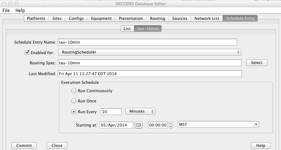
Figure : DECODES Database Editor (dbedit) - Routing Spec Scheduler Tab.
The fields of a Schedule Entry are:
Name – a unique name for the schedule entry
Enabled Checkbox – Only schedule entries that are enabled will be executed
The process name (RoutingScheduler in the above figure) – This is the name of the Routing Scheduler process that this schedule entry is assigned to. You can have several process, as described below.
Last Modified – tells you when this record was last written to the database
Execution Schedule – Determines when to run this entry. There are three choices:
Continuously – The entry is expected to be real-time. It is run when the assigned routing scheduler process is started.
Run once – The process is only run a single time at the specified “Starting At” date/time.
Run Every … – This is for a periodic routing spec.
The figure above shows a routing spec that is run every 10 minutes.
Routing Scheduler Processes
There is a single pre-defined Routing Scheduler process called “RoutingScheduler”. You can define more.
We make use of the Computations Editor. CCP users will be familiar with this application. Start the OPENDCS Launcher (“launcher_start”). Then hit the “Computations” button. Select the right-most tab “Processes”. You are presented with a list of known processes that do various things. Select the RoutingScheduler process and hit Edit. The figures below show the list and then the open Routing Scheduler.
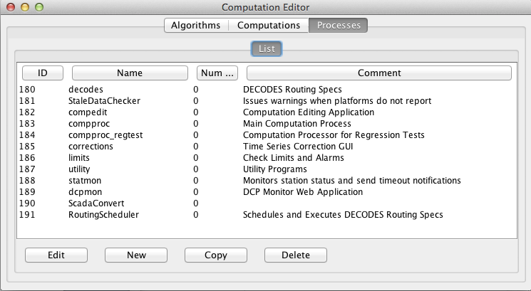
Figure : Comutation Editor - Processes Tab.
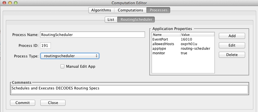
Figure : Computation Editor - Editing the RoutingScheduler Process.
In order to function as a Routing Scheduler, the process must be of the type “routingscheduler”. Select this from the pull-down list.
Settable Properties:
AllowedHosts – A comma-separated list of host names or IP Addresses. Leave blank for no restriction. Use this only if you want to restrict this process so that it can only be started on specific hosts.
monitor: Boolean (true/false) – Set to true to allow this process to be monitored by the GUI.
EventPort – Give this process a unique event port for the host on which it is running. This allows a GUI to connect to the process, show its status, and a scrolling list of events.
Starting and Stopping the Routing Scheduler
The command to start a routing scheduler process is:
routsched -a appname
… where appname is the name of the process (as defined in the process record. If you omit the –a appname argument, the name “routingscheduler” is assumed.
As with most DECODES programs you can also supply a –d argument to set the debug level to 1, 2, or 3; and a –l argument to specify a log file name.
If you are using a SQL DECODES Database …
If you are using a SQL database, the process will attempt to obtain a lock record. You can view locks with the utility:
complocklist
You can stop the process named “RoutingScheduler” with the command:
stopcomp –a RoutingScheduler
If you are using an XML DECODES database …
You should use the –k lockfile argument. For example
nohup routsched –d1 –k routsched.lock &
The process will create and maintain a lock file wherever you specify. To stop the process simply remove that file:
rm routsched.lock
In both cases (SQL and XML) after the lock is removed, the process will exit within 10 seconds.
Monitoring the Routing Scheduler Processes
OPENDCS 6 contains a new GUI for monitoring background processes. This can be used for the any process that maintains a lock in the database.
On the launcher bar, press Process Status. Adjust the center divider-bar so that you can view all of the processes, as shown below.
Each process updates a “heartbeat” in the database at least once every 10 seconds. It also shows its status as a short string.
You can click the “Events” checkbox in the table. The GUI will connect to the process and display events as they happen in the scrolling window.
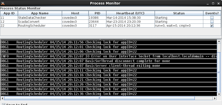
Figure : Process Monitor GUI.
DECODES Processing Modules
DECODES allows you to run Processing Modules on data after it has been decoded, but before it has been formatted and written to the consumer. Most of the modules perform some kind of computation to produce derived sensors. For example, the Rating modules take a water level input and derive a discharge or volume output.
Configuring Processing Modules
You configure the computation processor with an XML file in your DECODES directory. The default name for the file is “computations.conf”. It can be overridden with the –C argument:
rs … –C configFileName …
Or with the “compConfig” routing spec property. This allows you to have separate configurations for separat routing specs.
There is an entry in this file for each type of computation you want to support. Currently, two types supported. Your file should look much like the following.
<ComputationProcessor>
    <CompResolver class="decodes.comp.RdbRatingCompResolver">
        <Property name="dir">$DECODES_INSTALL_DIR/rdb-files</Property>
    </CompResolver>
    <CompResolver class="decodes.comp.TabRatingCompResolver">
        <Property name="dir">$DECODES_INSTALL_DIR/tab-files</Property>
    </CompResolver>
    <CompResolver class="decodes.comp.AreaRatingCompResolver">
        <Property name="dir">$DECODES_INSTALL_DIR/area-files</Property>
    </CompResolver>
    <CompResolver class="decodes.comp.StationExcludeCompResolver">
    </CompResolver>
    <CompResolver class="decodes.comp.TimeRangeFilterCompResolver">
    </CompResolver>
</ComputationProcessor>
This file installs ‘resolvers’ for the known processing modules. This file will not be overwritten when you install updates. This ensures clients who have custom processing modules that they will not be removed from the list. Unfortunately, it also means that if a new module is added during an upgrade, you will have to manually add it to the list.
If your file is missing any of the resolvers shown above you can add them manually (exactly as shown) to enable this feature in your system. The subsections below describe each module in more detail.
To have computations executed in DECODES, you must enable them. Either add the “-c” argument to the command line of your routing spec, or check the ‘Enable In-Line Computations’ checkbox in the routing-spec edit panel. For example, if my routing spec is called mvmDSS in the editable database, use this command:
rs –e –c mvmDSS
Rating Computations
There are three different types of rating computations. When a raw message is processed, it produces one or more time series containing your independent variables (e.g. STAGE). A computation processor can then use these to derive separate time series containing dependent variables (discharge). The output of the routing spec will contain both.
USGS RDB Rating Computations
The USGS publishes rating tables in a format called “RDB”. USGS distributes these files to other federal agencies. DECODES can use USGS RDB files to do calculations like:
Stage to Discharge
Elevation to Volume
You will need USGS RDB files with the shifts already calculated. An example is shown in Figure 35. Note the inclusion of the SHIFT column in the data. This is necessary.
This example also shows an “expanded” rating, meaning that the table includes the stored values (marked with an asterisk) and interpolated values at every .01 increment of the independent variable. DECODES is capable of doing its own logarithmic interpolation between stored points, so you do not need an expanded rating.
# //UNITED STATES GEOLOGICAL SURVEY http://water.usgs.gov/
# //NATIONAL WATER INFORMATION SYSTEM http://water.usgs.gov/data.html
# //DATA ARE PROVISIONAL AND SUBJECT TO CHANGE UNTIL PUBLISHED BY USGS
# //RETRIEVED: 2003-10-31 10:10:47
# //FILE TYPE="NWIS RATING"
# //DATABASE NUMBER=1 DESCRIPTION=" Standard data base for this site."
# //STATION AGENCY="USGS " NUMBER="05495000 " TIME_ZONE="CST" DST_FLAG=Y
# //STATION NAME="Fox River at Wayland, MO"
# //DD NUMBER=" 7" LABEL="Discharge, in cfs"
# //PARAMETER CODE="00060"
# //RATING SHIFTED="20031031100000 CST"
# //RATING ID="19.0" TYPE="STGQ" NAME="stage-discharge"
# //RATING REMARKS=""
# //RATING EXPANSION="logarithmic"
# //RATING BREAKPOINT1=1.00
# //RATING OFFSET1=0.80 OFFSET2=1.00
# //RATING_INDEP ROUNDING="2223456782" PARAMETER="Gage height IN feet"
# //RATING_DEP ROUNDING="2222233332" PARAMETER="Discharge IN cfs"
# //RATING_DATETIME BEGIN=20021001000000 BZONE=CDT END=23821230090000
EZONE=CST
INDEP SHIFT DEP STOR
16N 16N 16N 1S
0.80 0.12 0.12 \*
0.81 0.12 0.13
0.82 0.12 0.14
0.83 0.12 0.15
0.84 0.12 0.16
0.85 0.12 0.17
0.86 0.12 0.18
0.87 0.12 0.19
0.88 0.12 0.20
0.99 0.12 0.44
1.00 0.12 0.49 \*
1.01 0.12 0.53
1.02 0.12 0.57
1.03 0.12 0.62
. . .
Figure : USGS RDB Rating File Example.
Store the RDB Files in a Known Directory
Set up a directory under the DECODES installation to hold the RDB files. We recommend making a sub-directory called “rdb-files”.
Place your RDB files in this directory as you get them from the USGS. Many agencies are using WGET or RSYNC utilities to make sure they have the latest ratings.
The rating files can have any name. Typically, USGS will give them a name that contains the USGS Station Identifier (a long number from 7 to 15 digits) and the USGS database descriptor number, which uniquely identifies the sensor on that station. For example, the above rating file might be called “05495000-7.rdb”.
At the time of this writing, USGS maintains a national web-repository of RDB files at:
http://nwis.waterdata.usgs.gov/nwisweb/data/exsa_rat/**USGS-SITE-NUM**.rdb
Associate RDB Files with Independent Platform Sensors
Next you need to tell DECODES which parameters on which sites are to be the independent (input) values for RDB ratings. You do this by setting Platform Sensor Properties for the Independent (input) sensor.
Open dbedit and click on the Platforms tab. Select the desired platform and open it. Select the sensor for the independent variable. For example, if this is a stage (HG) to flow (QR) conversion, the independent variable would be stage (HG). Then press the “Sensor Properties” button.
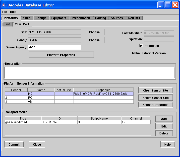
Figure : Select Platform Sensor and Press “Sensor Properties”.
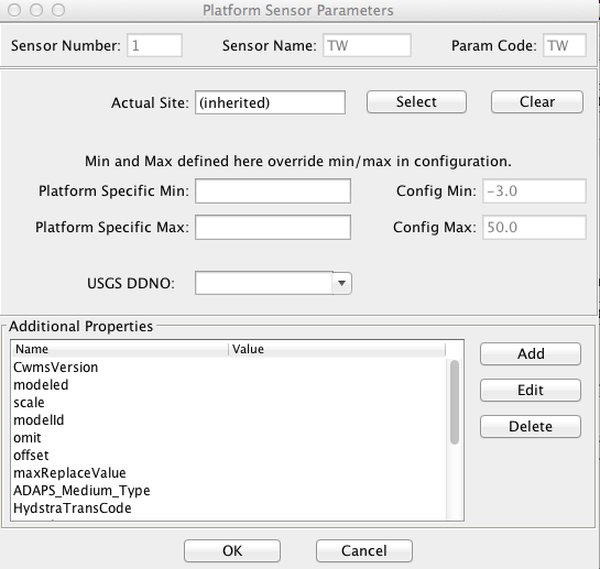
Figure : Platform Sensor Properties Dialog.
In this dialog you can set properties to control the rating:
RdbFile is set to the name of the RDB file to do the conversion. You do not need to specify a complete path name. The presence of this property is the trigger that causes the rating to be done.
depSensorNumber is the preferred way to set output (dependent) parameter attributes. Create a sensor in the configuration for the output dependent parameter. Assign data type codes, intervals, and properties as you usually would. Then in this dialog, simply set the sensor number for the output parameter.
ExceedBounds is an optional Boolean property (true or false). It tells the software how to treat values that are outside the entire table range. By default it is set to false, meaning that the lookup would just fail to produce a value. Set it to true to have the software extend the table through linear interpolation.
Legacy Method of setting Dependent Parameters.
RdbShef is set to the SHEF code for the output (dependent) variable. The example shows QR for river discharge.
Simple ASCII Table Files
Rating can be done with simple ASCII table files. An example would be the following file, which converts lake elevation into storage in Acre-Feet:
# CRVI4 - Elevation vs Storage (Ac-Ft) 28June2004
645, 0
650, 2
660, 100
670, 3120
680, 17720
690, 70730
700, 183710
710, 372680
715, 501670
720, 644470
Figure : Example of Simple ASCII Table File.
Just as you did for RDB file, you specify linkages by adding Platform Sensor Properties:
TabFile – The name of the table file to use on this sensor.
depSensorNumber – See description above under RDB Rating.
TabEU – The engineering units for the output value.
ExceedBounds is an optional Boolean property (true or false). It tells the software how to treat values that are outside the entire table range. By default it is set to false, meaning that the lookup would just fail to produce a value. Set it to true to have the software extend the table through linear interpolation.
Legacy Method of setting Dependent Parameters:
TabShef – The SHEF code for the output value.
TabName – The name for the output value.
USGS Area Ratings
Area ratings are done by table-lookup for a stage-area relation, and then multiplying the area times an average velocity sensor to produce discharge. Thus two independent variables must be present:
Stage (SHEF Code HG, HT, HP, etc.)
Water Velocity (SHEF Code WV, but sometimes called ‘XV’)
The computation does the following:
area = TableLookup( stage )
velocity = velocitySensor * velocitySensor-scale
discharge = area * velocity
You must attach properties to the stage-sensor to cause this to happen:
AreaFile – This is the name of the area rating file. This is the trigger that causes the computation to run.
DischargeShef – SHEF code for the computed discharge measurement.
DischargeName – Sensor name for the computed discharge measurement.
DischargeEU – Engineering Units abbreviation for the discharge measurement.
velocitySensor – The name of the sensor containing the velocity measurement.
If you want the velocity sensor value to be scaled, you must attach a property to the Velocity Sensor:
scale – A constant multiplier applied to velocity.
Y means that daylight time applies according to the normal domestic U.S. rules. That is, daylight time starts at 2 AM on the first Sunday of April, and ends at 2 AM on the last Sunday of October.
N means that daylight time never applies.
M means Manual. That is, the platform is set manually to the new time zone by the operator when the site is visited to collect the data.
In the case of manual daylight change, there are special rules: The time will be changed on or after the period starts. That is, the change to daylight time must occur after 2 AM on the first Sunday of April. The change back to normal time must occur after 2 AM on the last Sunday of October. Also, the operator must make the change after collecting the data, so that all data within a single EDL file has the same offset.
Note that the use of daylight time in general, and manual change in particular, is error-prone. You are strongly discouraged from this practice. The ideal situation is to program your recorder always in UTC, and to let DECODES make the conversions as needed when the data is parsed.
Saving Raw Archives
This is not really a configurable processing module. Rather it is built into the basic routing spec code.
This was added for a client that wanted a permanent record of all raw messages processed by DECODES. After each message is decoded, this module appends the raw data to an archive file.
To activate this module add a property in your Routing Spec called “RawArchivePath”. (Case is not important. “RAWARCHIVEpath” would also work.) This is the directory where you want archive files created.
You can include environment variables preceded by a dollar sign. These will be expanded when the code executes. You should specify a DATE timestamp somewhere in the string.
For example you could set it to:
$DCSTOOL_HOME/data/rawdata/fts/$DATE(yyMMdd).fts
And it will create the directories “data/rawdata/fts” under the OPENDCS installation. The file name will be in the format shown with a “.fts” extension.
Note: The date format take a string for the Java SimpleDateFormat class. See http://docs.oracle.com/javase/7/docs/api/java/text/SimpleDateFormat.html for a complete set of format possibilities.
You can change the periodicity of the archive with the $DATE specification. The file name is evaluated for each message. So to create a daily archive, as shown above, include date information down to the day.
Other possibilities:
For a monthly archive, leave off the day. E.g.: $DATE(yyMM)
For an hourly archive, add hour-of-day. E.g.: $DATE(yyMMdd-HH)
For an new archive every minute: $DATE(yyMMdd-HHmm)
In the RawArchivePath, you can also include:
$MEDIUMID – Will be replaced by the DCP Address (transport medium ID) of the station. You can use this to have separate archive files for each station.
$STATION - Will be replaced by the station(site) name used to determine the platform (used for data logger files). You can use this to have separate archive files for each station.
You can optionally include start and end delimiters which will be written to the archive before and after the raw data. To do this set the following properties:
RawArchiveStartDelim - written to the file before each message
RawArchiveEndDelim – written after each message
The delimiters can include C-style control characters like \n (linefeed), \r (carriage return), or \003 (ASCII End-Of-Text character). They can also include any of the settings described above with a dollar sign.
Delimiters make it easy to reprocess the file through DECODES.
The software will also purge archive files that are older than the specified maximum age. Add the property “RawArchiveMaxAge” to the Routing Spec. The value of this property can be strings like “1 year”, “6 months”, “30 days”, etc.
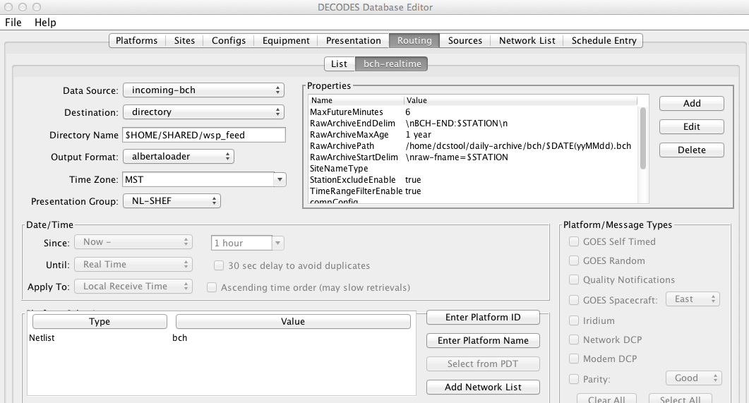
Figure : Routing Spec with Raw Archive Configured.
Time Range Filtering
For routing specs that run in real time, you may want to engage the Time Range Filtering module as a guard against outputting data too far into the future or the past. The module checks each time-series value’s time against the current date and time. If the time is outside a range that you specify, the values are set to MISSING so that they do not appear in the output.
The module is controlled by the following properties:
Name |
Type |
Default |
Description |
|---|---|---|---|
TimeRangeFilterEnable |
Boolean |
f alse |
Set to true to enable the Time Range Filter Module |
MaxFutureMinutes |
Integer |
6 |
Data with time-stamps more than this many minutes in the future will be discarded. |
MaxAgeHours |
Integer |
48 |
Data with time-stamps older than this many hours will be discarded. |
Excluding Stations from the Output
From time to time you may want to excluding stations from the output of a routing spec. For example, suppose it is malfunctioning and reporting garbage. You don’t want to modify all of your regional or functional network lists that may include this station, but you want the station ignored until it can be repaired.
The following properties allow you to do this. Define these properties in your routing spec:
Name |
Type |
Default |
Description |
|---|---|---|---|
StationExcludeEnable |
Boolean |
false |
Set to true to enable the Station Exclude Filter Module |
StationExcludeNLPrefix |
String |
exclude_ |
Stations on any network list with a name that starts with this prefix will be excluded from the output. |
When a message is excluded, the “Last Contact” and “Last Message” time in the showPlatformStatus utility will continue to be updated. It will also show an annotation like the following:
Excluded: Routing Spec Name netlist=***Network List Name*
Monitoring Schedule and Platform Status
GUI Platform and Routing Monitor
These are new features added in OpenDCS 6.2 RC10. The Launcher bar now contains two additional buttons:
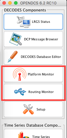
Figure : Launcher Frame with Platform and Routing Monitor Buttons.
By default, these buttons will be shown. If you want to hide the buttons, set the two new boolean properties in the Setup Screen:
showPlatformMonitor
showRoutingMonitor
Platform Monitor
The Platform Monitor screen is shown below in Figure 41. The list may be sorted by clicking any of the column headers. The columns are:
Site assigned to the platform
Designator assigned to the platform. Recall that the combination (Site, Designator) is unique.
Last contact time – For GOES stations, this will be the last message time. For Polled data loggers, it will be the last time the station was contacted.
Last Message Time
Last Quality Codes – See list of possible quality/failure codes in the LRGS users guide. Typical codes for GOES include G=Good, ?=Parity Error, T=Overlap Time Window, U=Unexpected.
Last Error Time – If no errors have occurred in the last 48 hours, this field is blank. Otherwise it is the time that a WARNING or more severe error was encountered when processing data from this platform.
Routing Spec – The last routing spec that processed a message from this platform.
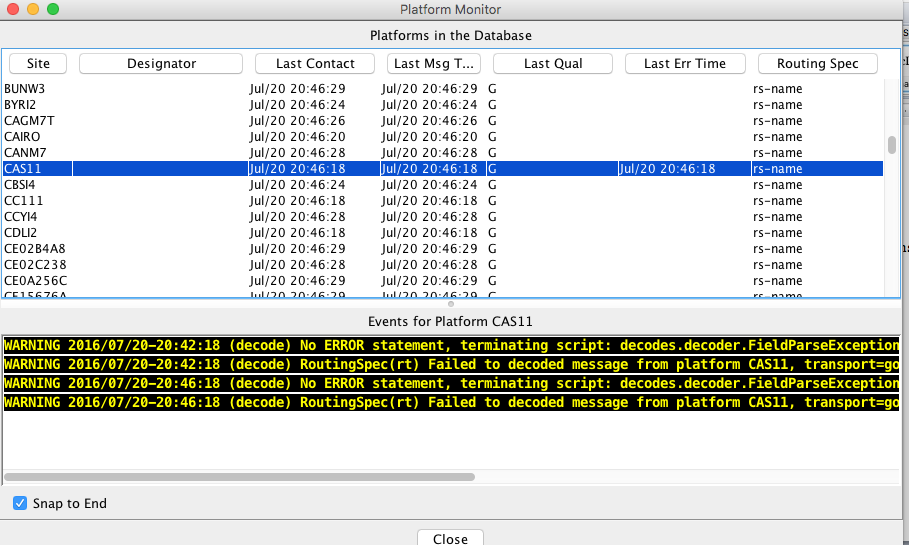
Figure : Platform Monitor Screen.
Click on a platform in the list. The lower panel is filled with recent events that were recorded for this station.
Routing Monitor
The Routing Monitor screen is shown below in Figure 42. The top panel shows routing specs defined in your database.
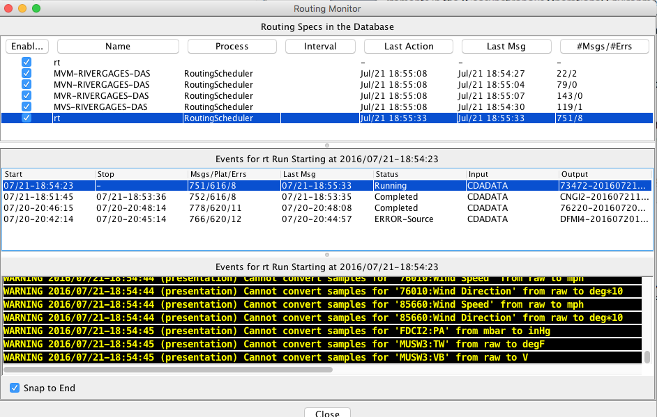
Figure : Routing Monitor Screen.
Text Mode Utilities
These are new features added in OPENDCS 6.0.
To monitor status of your schedule entries:
showScheduleStatus [–h hours] [entry-name…]
Where
-h hours Only show status records updated in the last number of hours (default=12). To only show the current status, use –h 0 (zero).
entry-name Only show status for specified entry name(s). You may specify more than one. If none specified then status for all schedule entries is shown.
The system will keep track of your data retrievals and decoding by platform:
Date/Time of last station contact
Date/Time of last successful message retrieval
Date/Time of last error (either transmission or decoding)
An annotation explaining the nature of the error.
You can view the current platform status list with the program:
showPlatformStatus [–n NetworkList] [-e #hours] [-e current]
If you specify a network list with the “-n” argument, only the platforms in the list will be displayed. Otherwise all platforms are displayed.
You can specify a threshold with the –e argument:
-e 3 Only show platforms with an error in the last 3 hours.
-e 1 Only show platforms with errors in the last hour.
-e current Only show platforms that are currently in an error state. (That is, the most recent error has occurred since the most recent message retrieval.)
The output of the program is a plaintext report designed to be easily imported as a CSV file into a spreadsheet. For example:
    Platform Name         Last Contact         Last Message     FailCode      Last Error       Annotation
====================  ===================  ===================  ========  ===================  ==========
GRIV-camp           , 03/11/2014-11:03:20, 03/11/2014-11:03:20, G       , 03/12/2014-14:32:17, Stale: No data
STAV-camp           , 03/11/2014-11:03:20, 03/11/2014-11:03:20, G       , 03/12/2014-14:32:17, Stale: No data
MSC-005-camp        , 03/11/2014-11:03:20, 03/11/2014-11:03:20, G       , 03/12/2014-14:32:17, Stale: No data
In order to detect stale data, you will need to run the daemon:
staleDataChecker [-n netlist] [-a appname]
The –n argument may appear more than once for checking platforms on a set of lists. The application name specified with the –a argument defaults to “StaleDataChecker”. This must match a process name in the computation editor.
To set this up, start the computation editor either with the “compedit” command or from the Computations button on the launcher panel. Click on the Processes tab along the top. Find the process called “StaleDataChecker” end edit it. It should look something like Figure 11‑43
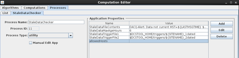
Figure ‑: StaleDataChecker Process Record.
If this record doesn’t exist, you will need to create it. This can happen if you upgraded to OPENDCS 6 from a previous toolkit.
In this case create a new Process called “StaleDataChecker”. Set the process type to “utility”.
You can specify properties as follows:
StaleDataMaxAgeHours (default=6) – if a platform goes this long without receiving a message flag it as stale.
StaleDataCheckMinutes (default=1) – Check this often for stale data.
StaleDataTriggerFile1 (default = blank) – Name of first trigger file to create (see below).
StaleDataTriggerFile2 (default = blank) – Name of first trigger file to create (see below).
StaleDataFileContents (default = “DACQ-Alert: Data not current MST=${LASTMSGTIME} ${SITENAME}”) – This is the string placed in the trigger file(s).
When a station goes stale, one or two trigger files can be created. You specify the complete path name with the two File1 and File2 properties. The properties can contain strings like:
$HOME – your user’s home directory
$DCSTOOL_HOME – the installation directory of the toolkit
$DCSTOOL_USERDIR – Your individual user directory of a multi-user toolkit installation.
$SITENAME – the name of the site associated with the platform.
Likewise the StaleDataFileContents property can also contain these strings along with a special string $LASTMSGTIME which will be replaced with the time that this platform last received a message.
Data Acquisition & Decoding Events
As of OpenDCS 6.1 selected events relating to data acquisition and decoding are stored in the database.
Each Routing Spec will create these events as it runs, regardless of whether the Routing Spec was started from the scheduler or from the “rs” command line.
Events are associated with routing-spec runs (i.e. the running of a particular routing spec at a given time). If platform related, events are also associated with a platform.
The OpenDCS 6.1 DCP Monitor contains web pages allowing you to search stored events by routing spec run and by platform.
Only INFO, WARNING, FAILURE, and FATAL events are saved in the database. Debug-level events are stored in the process’ log file, but never the database.
Events are purged after a configurable number of days. The DECODES Setting value eventPurgeDays is an integer number of days.
Periodically, each routing spec will attempt to purge events older than the specified number of days. The default number of days is 5.
Polling and Listening for Data Loggers
OpenDCS supports a direct, automated interface for data loggers:
Polling a data logger via old-style modems
Polling a data logger via TCP socket. This can also be used for data loggers with cellular modems and a static IP address.
Listening for incoming TCP connections from remote data loggers. This can be used for data loggers with cellular modems and dynamic IP addresses.
Once data is received from an electronic data logger (EDL) it is represented as a message with an EDL header. These messages can be processed directly through DECODES. However, a recommended way is to use LRGS to store raw message data. This arrangement is illustrated in Figure 44.
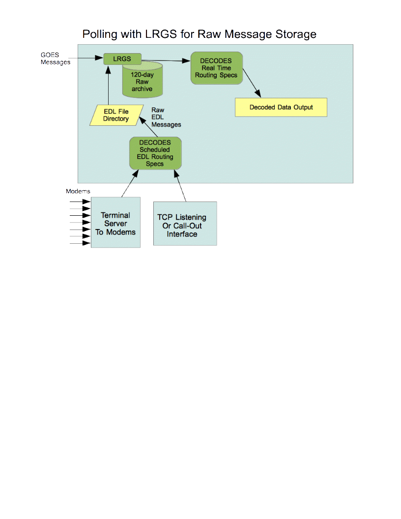
Figure : Polling Data Saved in LRGS.
Here’s how it works:
Raw polled EDL message received by a routing spec configured with one of the polling or listening interfaces described in this chapter.
This routing spec saves data in “raw” format in a directory.
The LRGS is configured to watch this directory for incoming EDL files (See LRGS manual for instructions on how to do this).
LRGS stores raw EDL messages for specified number of days (e.g. 120).
A real-time DECODES routing spec retrieves EDL messages, decodes them, and puts decoded output somewhere.
Enumeration Records
If you upgraded from a release that existed prior to the polling and listening capability, you may need to enter some Enumeration Records manually.
Start the Reference List Editor program with the ‘rledit’ command.
On the Enumerations Tab. Select the “Port Type” enumeration. If an entry doesn’t already exist for TcpListen, you must create it. Click the Add button and fill out the form as shown below. The Executable Java Class must be entered exactly as shown:
decodes.polling.ListeningPortPool
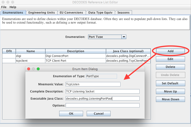
Figure : Enter Enum Record for TcpListen.
Also on the Enumerations Tab, select the Transport Medium Type enumeration. If an entry doesn’t already exist for incoming-tcp, click the Add button and fill out the form as shown below. The Mnemonic value must be exactly “incoming-tcp”.
Also make sure the following records exist:
Mnemonic Value: digi
Description: Digi ConnectPort for Modem Interface
Exec Class: decodes.polling.DigiConnectPortPool
Mnemonic Value: TcpClient
Description: TCP Outgoing Client
Exec Class: decodes.polling.TcpClientPortPool
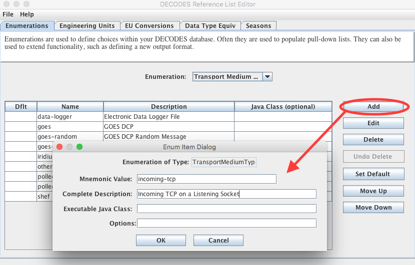
Figure : Enter Enum Record for incoming-tcp Transport Medum type.
Also make sure the following records exist:
Mnemonic Value: polled-tcp
Description: Polled TCP Socket
Mnemonic Value: polled-modem
Description: Polled via modem
For these records, the Executable Java Class may be left blank.
Next, select the Data Source Type enumeration and add a new record with mnemonic “Polled” and exec class “decodes.polling.PollingDataSource”. As shown below:
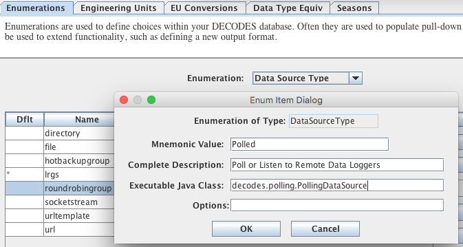
Figure : Data Source Type for Polled & Listened Loggers.
Before exiting the Reference List Editor, Click File – Save to DB.
Make sure you have an Enumeration called PortType. If not, you will find a file called “Polling.xml” in the $DCSTOOL_HOME/edit-db/enum directory. Run the following commands
cd $DCSTOOL_HOME
bin/dbimport edit-db/enum/Polling.xml
On Windows systems you can execute these commands inside a DOS CMD window:
cd %DCSTOOL_HOME%
bindbimport edit-dbenumPolling.xml
Finally, older databases may be missing the “Logger Type” enumeration entirely. Run the reference list editor as described above. On the Enumerations tab, in the Enumeration pull-down list, if there is no “Logger Type” enumeration, then:
Exit the reference list editor (saving any changes you may have already made).
When you last updated OpenDCS, it should have placed a file called “LoggerType.xml” in the edit-db/enum directory. Run the following:
cd $DCSTOOL_HOME
dbimport edit-db/enum/LoggerType.xml
Then restart reference list editor. You should now see the Logger Type enumeration.
Platform Designator
If you open a platform record in the database editor, you see a field called “Designator”. This is a free-form annotation that you can use to denote platforms of a given type. Many use it to see at a glance which platforms are GOES, as opposed to different types of data loggers. In the following snapshot, “camp” indicates that this is a polled logger made by Campbell Scientific, Inc.
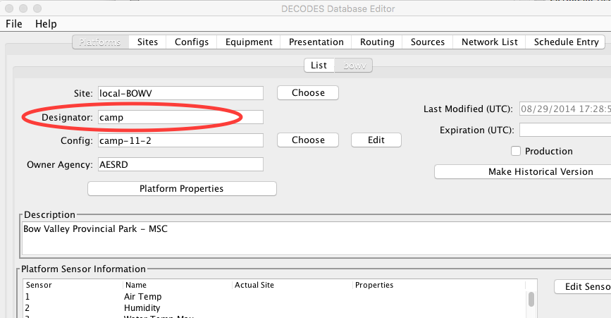
Figure : Assigning a Platform Designator
Assigning a designator is not strictly necessary in most cases. The rule is that you may have more than one platform at a given site, but if you do so, they must have different designators.
In the Decodes Settings panel, (Click Settings from the main launcher), find the ‘PlatformListDesignatorCol’ variable and set it to True. Then restart the database editor and go to the Platform tab.
There is now a separate column for Designator which you can use to sort the list. Note also that designator appears as part of the platform name.
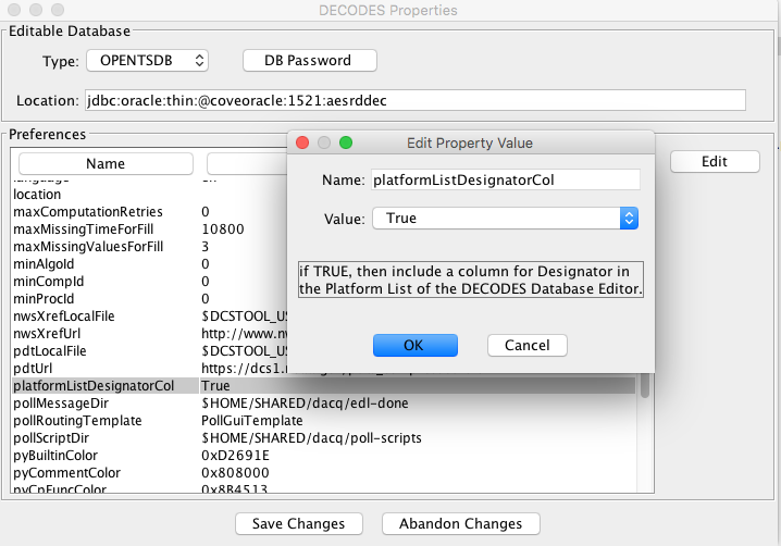
Figure : Set platformListDesignatorCol to True.
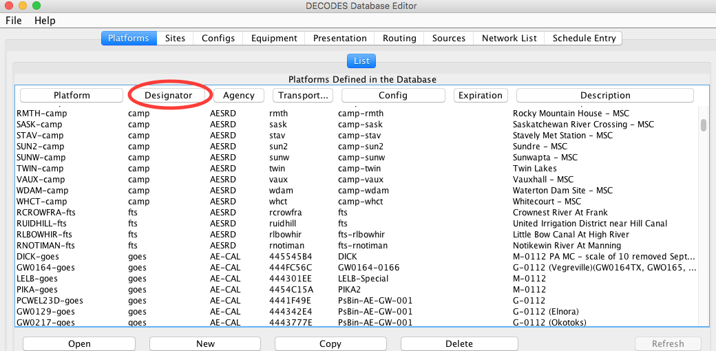
Figure : Click ‘Designator’ Column Header to Sort List.
Modem Polling Routing Spec
Modem Polling Data Source
On the “Sources” tab of the database editor, create a data source record for your Digi ConnectPort device:
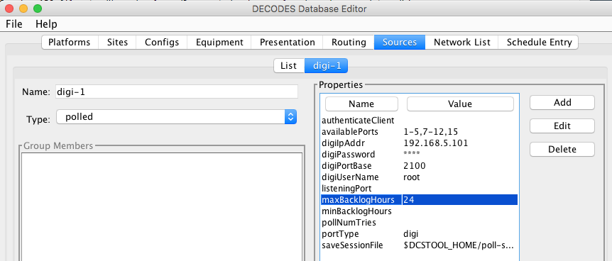
Figure : Digi ConnectPort Polling Data Source Record.
On the left, select “polled” for data source type. Then fill out the properties relevant for the modem polling. Hover over the property names for tool-tip help. The properties are:
availablePorts: The Digi ConnectPort has 32 numbered ports. Enter here a list of ports or port-ranges that have modems installed. This defines the modems in the pool.
digiIpAddress: Enter the IP Address or Host Name for the Digi device on your network.
digiUserName: Usually ‘root’. This is the user name that the software uses to set up serial parameters like baud, stop bits, etc.
digiPassword: The password required to login as the digiUserName
digiPotBase: Usually 2100. This is the TCP base port for accessing the device serial ports.
maxBacklogHours: When polling, this is the maximum backlog that the software will request from a logger.
portType: digi
saveSessionFile: Optional file name for saving each raw modem session. The session shows all the interaction between the base station and the logger, not just the captured message data. A reasonable setting could be:
$DCSTOOL_HOME/poll-sessions/$sitename-$DATE(yyyyMMdd-HHmmss).poll
Warning! If you do this, you probably want to have some schedule script in place to purge the session files after they reach a certain age.
Platform Transport Medium
For each logger that you will access via modem, you must create a transport medium:
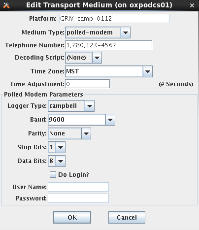
Figure : Modem Transport Medium
For Medium Type, select “polled-modem”. The rest of the fields will then adjust appropriately:
Telephone Number
Decoding Script: If you are only collecting raw logger data for feeding into an LRGS, as described above, you can leave this as (none).
Time Zone: Select or type the time zone in which the logger represents times in the collected data.
Logger Type: This determines the protocol used to communicate with the logger. See the section on Logger Types and Poll Scripts below.
Serial Parameters: Baud, Parity, Stop Bits, Data Bits
If it is required that OpenDCS logs into the logger, you can enter user name and password here. The Poll Script (described below) can use these fields for authenticating on different logger types.
Network List of Modem Stations
After you have added transport media to your modem Platform records. Create a network list of the modem stations that you want to poll.
Select “polled-modem” for Transport Medium Type, then click Select Platforms. All platforms with a polled-modem transport medium will be shown for you to select from. In the following figure we have hidden the actual telephone numbers, which will show up as your Transport ID.
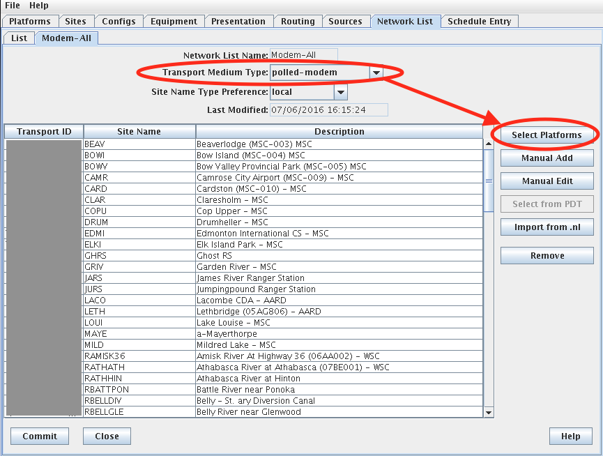
Figure : Network List of Polled Modem Stations.
The Routing Spec
Finally, create a routing spec, which will tie all the pieces together.
Select the digi data source. When you do this, the software will recognize that this is not a GOES/LRGS type data source and it will disable several fields:
Date/Time range is not applicable. Each run of the routing spec will attempt to poll all of the stations in the network list once.
Selecting from PDT or GOES Channel is not applicable for polled stations.
Platform Message Types is an LRGS criteria and not applicable.
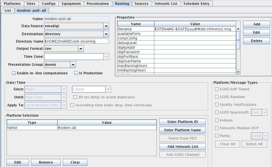
Figure : Routing Spec for Polled Modem Stations.
Also note in the above example that Output Format = raw, meaning no decoding will be done. Rather, the raw data collected from the station will be saved.
We have chosen the directory $HOME/SHARED/edl-incoming as the destination. Thus each polled-message will be saved as a separate file in that directory. Note the “filename” property is set to:
$SITENAME-$DATE(yyyyMMdd-HHmmss).msg
Thus each file will have the station and a date/time stamp.
When the routing spec is run, it will use all of the available modem ports in the data source pool to poll all of the stations in the list. The property “pollNumTries” (default=3) determines how many times each station will be tried.
Once all of the stations have been successfully polled, or tried the specified number of times, the routing spec will terminate.
Schedule Entry to Poll Every Hour
On the “Schedule” tab, we have created a schedule entry to run the routing spec every hour.
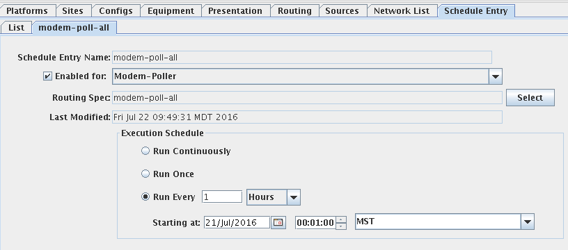
Figure : Schedule Entry to Poll Hourly.
If the schedule entry record is unfamiliar to you, see Chapter 9. Note here that we are running the “modem-poll-all” routing spec every hour starting at 1 minute after the hour. The process called “Modem-Poller” will do the execution.
Round Trip through LRGS
Refer to the OPENDCS6-LRGS-UserGuide chapter 10. The preferred mechanism for polling is:
A routing spec that saves raw EDL message data to a directory, as described above.
The LRGS is configured to watch that directory for incoming EDL files. Thus after a poll is complete, the file is saved and then ingested into the LRGS day-file archive. The polling interface adds the EDL header as required by the LRGS.
A separate routing spec now retrieves the EDL data from the LRGS and decodes it.
This may seem somewhat indirect, but it has the following advantages:
EDL data is automatically backed up in LRGS short term archive (typically 90 days). So if it needs to be reprocessed later, you don’t have to poll the station again.
EDL data can be easily shared among multiple computers, applications, and agencies.
TCP Polling Routing Spec
Polling through TCP is simpler than polling through modems. The following discussion will rely on the previous section on modems. Please read that section first.
Polled TCP Data Source
Set up the TCP Polling Data Source as shown below. Type is “polled”. Set the portType property to “tcpclient”. Available ports here is a simple number representing the maximum number of simultaneous polling sessions to allow. It is a way to throttle the polling.
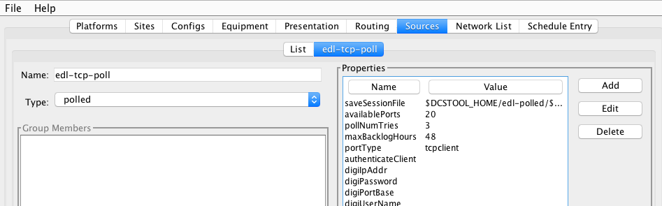
Figure : TCP Polling Data Source Record.
Polled TCP Transport Medium
The polled TCP transport medium is shown below.
Medium Type is “polled-tcp”
Enter the host name or IP address followed by a colon and the TCP port number that the station is listening on. Many stations listen on port 23 which is the standard port for Telnet.
All other parameters are similar to those shown above for polled modem.
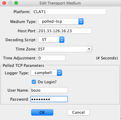
Figure : Polled TCP Transport Medium
TCP Listening Routing Spec
Listening Data Source
On the “Sources” tab of the database editor, create a data source record for your listening socket.
Under Type, select “polled”
Set the listeningPort property to the TCP port number (default is 16050)
Set the portType property to tcplisten
Set the availablePorts property to the number of clients you would like to be able to serve simultaneously (default = 50)
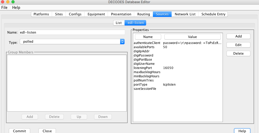
Figure : Listening Data Source Record.
The listening socket supports an optional client login. That is, for security reasons you may want the client data loggers who connect to login to this server. If this is the case, set the authenticateClient property. The format of the property value is:
password=<prompt>=Required Password Value
Thus in the example shown below, when a client EDL connects, the server will send the prompt: \rnpassword:
That is, carriage return, linefeed, followed by the string ‘password: ‘
The EDL must then response with the password: “ToPsEcReT”. If it fails to do so, the connection is aborted, and a warning message is issued to the routing spec log.
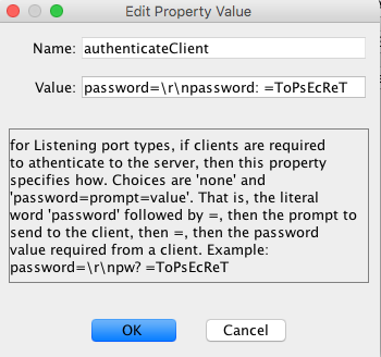
Platform Transport Medium
Open the Platform record for the loggers that will connect to the listening port. Create a transport medium record with Medium Type set to “incoming-tcp”:
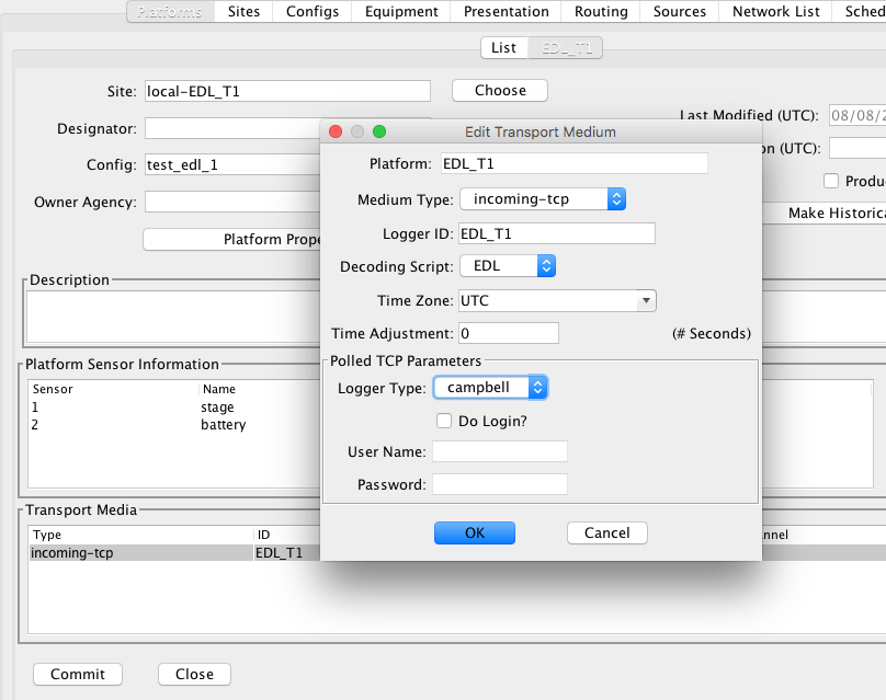
Figure : Incoming TCP (listening socket) Transport Medium.
The fields in the Transport Medium dialog are:
Medium Type: Set to “incoming-tcp”
Logger ID: Set to the unique string that the logger uses to identify itself to the server. For the current implementation, the logger must send a single line of text with containing an ID used to identify the station.
Decoding Script: The script in the configuration used to decode this type of message. This may be left blank if you only want the raw data.
Time Zone: Set to the time zone that the logger uses to encode times in the data sent to the listening socket.
Logger Type: This specifies the name of a Poll Script (see below). The script is used to interact with the station after it connects.
Do Login, User Name, and Password: If the station requires that the server logs into it, check this box and enter the login info here.
Listening Socket Session
After the EDL connects to the listening socket, a session proceeds as follows:
If required, the logger must login to the listening server. The “authenticateClient” property in the routing spec or data source controls this.
The station must send a single line containing a unique ID so that the server can identify the station. This must match an entry in the Logger ID of a transport medium.
The specified polling script is executed. This interacts with the logger to retrieve the desired data for the desired time range, etc.
The script determines what data is captured to be stored as a message
The session is terminated after the script is completely executed, or the logger terminates the connection.
If any data has been captured, it is processed as a DCP message.
Network List of Loggers Allowed to Connect
On the Network List Tab of the database editor, create a network list. Set the Transport Medium Type to “incoming-tcp” and add all of the platforms that are allowed to use the listening socket.
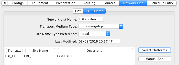
Figure : EDL Listen Network List.
The Routing Spec
The Routing Spec ties the pieces together. The example below shows a routing spec that opens the listening socket and then saves raw data in the directory $LRGSHOME/incoming-edl. Note the following:
Data Source: edl-listen – this is the data source record we set up above
Destination: Directory – this means that each message (session) will be saved as a file in the named directory.
Output Format: raw – no decoding is done.
Platform Selection: Netlist EDL-Listen – this is the network list that we created above. It determines what platforms are allowed to connect and send us data.
Date/Time Ranges are not used. A Listening Socket runs continuously, accepting client connections as they come.
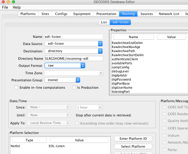
Figure : EDL Listening Routing Spec.
Logger Types and Poll Scripts
The Logger Type setting in the transport medium determines the protocol used to communicate with the remote logger after a connection has been established.
Like many of the pull-down lists in DECODES, logger types are populated by Enumeration records that you can edit in the Reference List Editor. Start the Reference List Editor from the Windows Start menu or from the “rledit” command. Select the Logger Type enumeration. Here you can create or modify logger types.
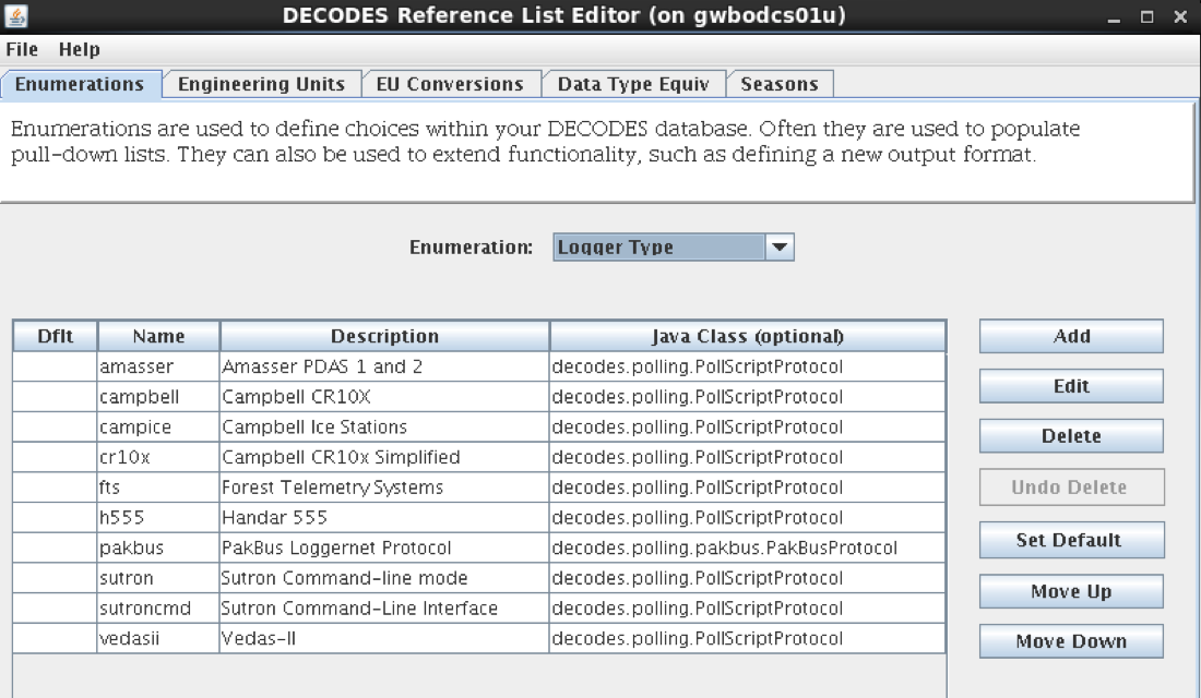
Currently there are two separate Java Classes that implement logger protocols:
decodes.polling.PollScriptProtocol – Uses a script file to communicate with the logger via a command-line interface
decodes.polling.pakbus.PakBusProtocol – Communicates with a Campbell Scientific logger using Campbell’s proprietary PakBus protocol.
Most loggers accept some kind of command-line syntax. We describe the PollScriptProtocol first. The following snap shows the complete enumeration record for the “fts” logger type. Note that under options, we specify the name of the script file (“fts.poll” in this case.)
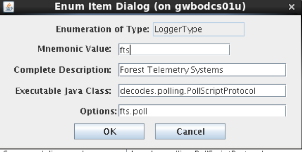
Where are the script files located? This is specified by the DECODES Setting called “pollScriptDir”:
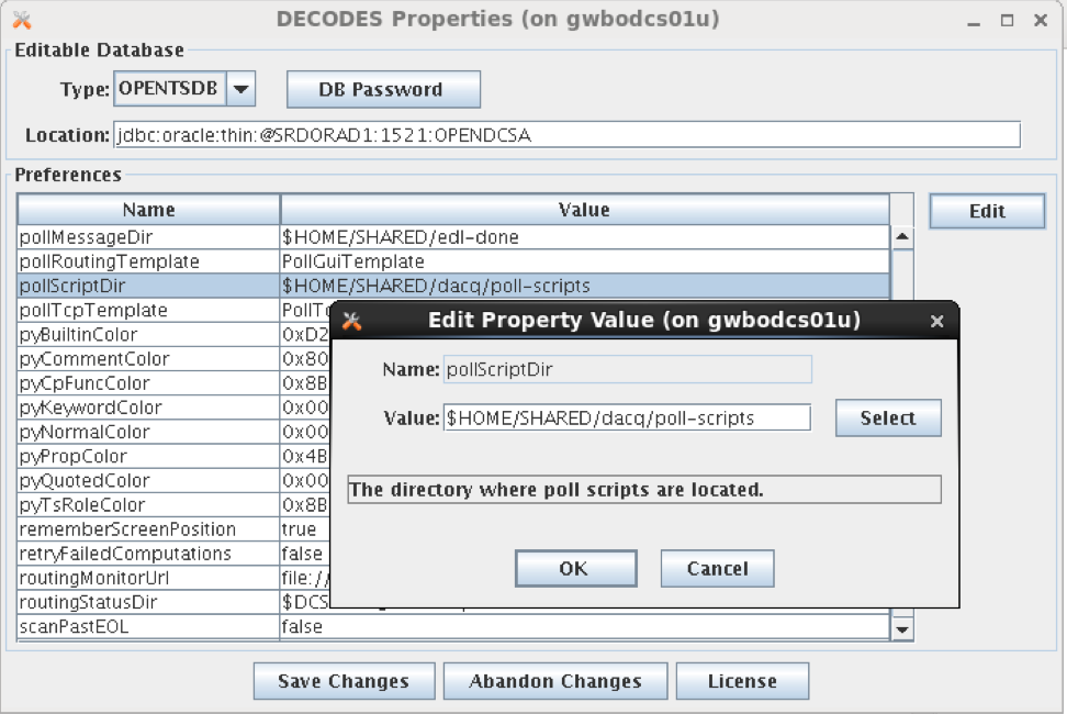
Poll Scripts
Poll Scripts provide a simple language to control the interaction with a logger. They are used for polled TCP and Modem stations, as well as for Listening Socket stations.
The Decodes Setting “pollScriptDir” tells the system where to find your poll scripts. The default is $DCSTOOL_HOME/poll-scripts.
This section will explain the syntax for poll scripts.
Poll Scripts are ASCII text files with commands, one per line. Blank lines and comment lines that begin with ‘#’ are ignored. The supported commands are:
XMIT “string in quotes”
Transmits a string of data to the logger. Normal C and Java- style escape sequences are supported like \n (newline), \r (carriage return), etc. It may also contain the following special strings:
${START} – the start time for data retrieval formatted according to the STARTFORMAT setting (see below)
${SITENAME} – the preferred name of the site for the platform being polled.
${USERNAME} – from the transport medium record, if assigned.
${PASSWORD} – from the transport medium record, if assigned.
STARTFORMAT “date/time format in quotes”
The polling interface will determine the last time it communicated with a given logger. This can be limited by a backlog setting. Example, if it last communicated with a logger 2 weeks ago, but max backlog is set to 12 hours, then the $START time will be the current time minus 12 hours.
The string after STARTFORMAT should be acceptable to the Java SimpleDateFormat class. See on-line documentation for this class.
Example:
STARTFORMAT “yyyy/MM/dd-HH:mm”
XMIT “start=$STARTn”
CAPTURE ON
This command turns capture on. Any subsequent data received from the station is considered part of the message data to be saved.
CAPTURE OFF
Turn capture off
WAIT #seconds
Causes the script to unconditionally pause for the specified number of seconds.
WAIT #seconds, “expected string in quotes”
Cause the script to wait the specified number of seconds, or until an expected string is received. For example, if you are expecting a prompt “>” from the station, you could do this:
WAIT 10, “>”
If more than one possibility is possible you could have multiple strings separated by a pipe character. For example, if the prompt could be a “>” or the string “cmd:”, you could do:
WAIT 10, “>” | “cmd:”
If the expected string is not received in the given number of seconds, execute of the script will proceed.
WAITR #seconds, “required string in quotes”
This is identical to WAIT except that a correct response is Required. If one of the expected strings is not received then the session terminates.
WAITX #seconds, “Bad String”
The X means exclude. Use this to detect strings that indicate problems on the logger.
LOOPWAIT #iterations
…
WAIT …
ENDLOOP
This block of code allows you to loop, trying a number of times for a desired result. For example, the following tries 5 times to send a carriage return and then wait for the string “Operator Mode”:
# Try 5 times to get to the Main menu
LOOPWAIT 5
XMIT “r”
WAIT 15, “Operator Mode”
ENDLOOP
PakBus Protocol
In the enumeration record for pakbus, it is not necessary to specify a poll script:
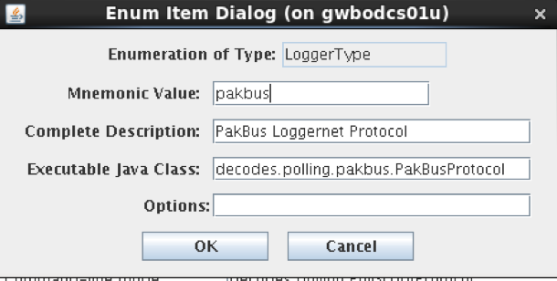
The PakBus protocol works well with late model Campbell loggers such as the CR1000 and CR3000. For older models, you may have more luck with the Campbell command line interface and a poll script, as described in the previous section.
The DECODES PakBus interface does the following:
Retrieve the logger’s Table Definitions.
Query the logger for data from a specific table (e.g. “Hourly” for the desired time range).
Since retrieving table definitions can be a lengthy process, the system will cache table definitions in local files for a limited time.
The DECODES Setting “pakBusTableDefDir” defines the directory where these temporary table definition files are cached.
The DECODES Setting “PakBusMaxTableDefAge” defines the maximum age a cached file can be before a new one will be downloaded from the logger. The default is “hour*48” or 48 hours.
Once a table definition is downloaded you can view the table definitions with a new utility:
printPBTableDefs filename
For the second step (query logger for data), the software needs to know the table name to query. The default if none is specified is “Hourly”. You can make a global default with the DECODES setting “pakBusTableName”.
Then, if you have some odd loggers that require a different name, add a Platform property (DECODES Database Editor – Platforms Tab – Open Platform – Click the Platform Properties button). The name of the property should be “pakBusTableName” with the desired table name as property value.
DCP Performance Measurment Sensors
This feature was added for OpenDCS 6.8 RC08.
Some data sources have the concept of performance measurements that are typically included in the header of a message. This feature allows you to output these measurements as if they were sensors.
To do this, you must first add the sensors to the DECODES Configuration records. Open the configuration for the platform(s) for which you want performance measurements and click the “Add DCP PMs” button:
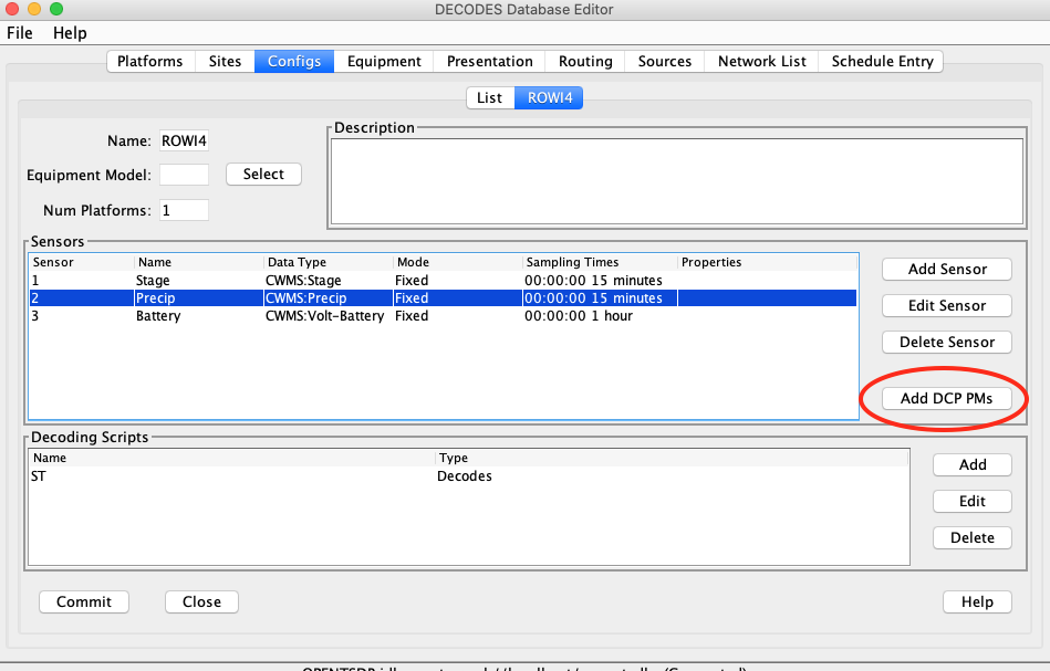
Select the performance measurements you want from the list:
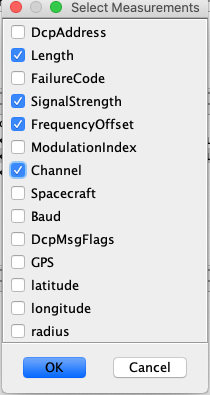
Sensors will be added to the configuration for the PMs that you selected:
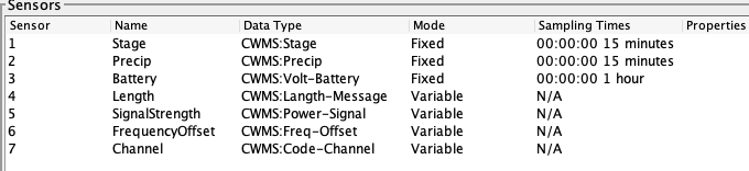
Next, open each sensor by double clicking on it and add/modify the data type codes. The sensors are set to “Variable” recording mode by default, meaning that they will be time-stamped with the message time. You can set them to fixed and provide an interval if you want, just like any other sensor.
You can also set any sensor properties you need here.
Next, open the decoding script and add units.
The last step is in your routing spec. Open the routing spec in the editor and add/set a property called “includePMs”. It should be set to a comma-separated list of performance measurements you want included in the output. The following figure shows a routing spec that will output DcpAddress, (message) Length, ans Signal Strength.
Note: Be sure that the PM names match the sensor names that you added, which will match the names in the select dialog: